
Creating a System Model
Tutorial Goals
- Use the hardware blocks to develop a system model.
- Combine traffic generators and processing blocks to define the transaction rate and content.
- Evaluate the performance of bus and DMA.
- Examine the overhead of an external or off-chip DRAM.
Model Location
Open this model in VisualSim from the following location:
$VS/doc/Training_Material/Architecture/Tutorial/Architecture_Exploration/Using_DMA/
Model Introduction
This model demonstrates the
use of the Hardware Architecture Library in VisualSim. The session
combines the performance and architecture libraries in assembling a
detailed system model. This session helps you understand how to
connect and configure the blocks into a model.
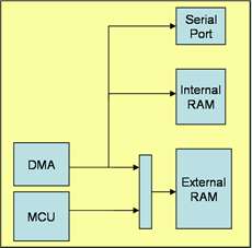
Figure 1: Block Diagram of the System Architecture Model
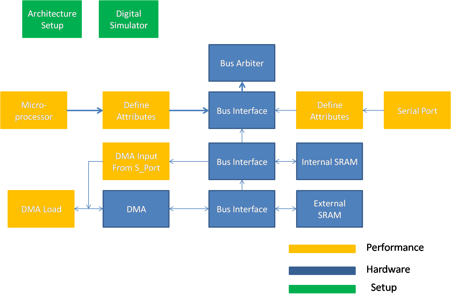
Figure 2: VisualSim model of the System Architecture
List of Block Used
Sl No
|
Library Block
|
Description
|
1
|
Digital Simulator

ModelSetup > Digital
|
This
Simulator is used to model protocols, hardware, and mapping of behavior
to architecture. This simulator is used when the model is being
triggered as an event or based on time. The Digital Simulator
implements the discrete-event Model of Computation (MoC). This
Simulator maintains a notion of current time, and processes events
chronologically in this time.
|
2
|
Traffic

Traffic > Traffic
|
Traffic
block outputs a new Data Structure (DS) at time intervals specified by
the "Time_Distribution" setting. A Data Structure is a transaction
containing a list of Field Names + Values.
|
3
|
Expression_LIst

Behavior > Expression List
|
The
Decision/Expression_List blocks execute a sequence of expressions in
order. The default block contains one input and one output. The user
can add multiple input and output ports.
|
4
|
Text Display

Result > Text > Text_Display
|
Displays
the values arriving on the input port in a text display dialog. This
block buffers the display data and updates the screen after the buffer
is full.
|
5
|
TimeDataPlotter

Results > TimeDataPlotter
|
This
block plots the incoming data on the Y-Axis against the current
simulation time on the X-axis. Every wire connected to this block input
is considered a separate dataset and plotted separately.
|
6
|
Architecture Setup

Hardware_Setup > Architecture_Setup
|
This block handles all the address mapping, routing, plotting, statistics and debugging for the Hardware Modeling components.
|
7
|
DMA

Hardware_Devices > DMADatabase
|
DMA block that represents a memory controller that sits between the Processor or bus or I_O Block and the Memory bank.
|
8
|
DMA Database

Hardware_Devices > DMADatabase
|
This
block is a lookup table or database containing rows and columns. Each
row is a data structure. Each column of the row is a field of the data
structure.
|
9
|
RAM

Memory > RAM
|
This
block combines the operation of a basic memory controller (delay
function) and the memory array. The block handles pre-fetch, read,
write, refresh, and controller operations. The block can be interfaced
to any Bus or Memory Controller.
|
10
|
Delay

Traffic > Delay
|
This block delays the incoming Data Structure by the value specified in the Delay Parameter.
|
11
|
Parameter

Model > Parameter >Parameter=
|
Parameter is a variable containing a constant that can be any VisualSim data type, function and/or a RegEx expression.
|
12
|
Initialize

Full Library > Source > Event > Initialize
|
This
block can be used to generate a value at the start of a simulation at a
zero delay. User can set an Initial Order, 0 being the lowest priority
and higher values fire before lower priority Initialize blocks.
|
13
|
Statement

Full Library > Defining Flow > Basic Processing > Statement
|
This
is a block that executes a mathematical expression on each of the four
Field_Statement lines based on the Data Structure Expression language.
|
14
|
If_Else

Full Library > Defining Flow > Basic Processing > If_Else
|
This
is a programming if-else operation. If the condition in the
"If_Statement" equates to a true or 1, then the line numbers listed in
the "if_Execute" are executed.
|
15
|
Variable List

ModelSetup > Variable List
|
The
block is used to define memory locations that can be used
in Expression, Decision, Basic Processing (Statement etc.),
Smart_Machine, and Virtual_Machine blocks.
|
16
|
BusArbiter

Hardware Devices > BusArbiter
|
The
Linear_Bus or Bus Arbiter block is the Arbiter for a Linear Bus or Bus
Interface. The Linear bus is a shared bus topology with an arbiter.
|
17
|
BusInterface
Hardware Device > Bus_Interface
|
The
Linear_Port or Bus Interface block is used to connect the devices to
the Linear_Controller Bus. The block has a queue for each
port. The incoming transactions are queued and the head of the queue is
sent to the Controller Queue.
|
18
|
IN

Behavior > IN
|
This
block accepts incoming Data Structures or tokens from any
OUT/MUX/uEngine/Virtual_Machine blocks and sends a value on the output
port. The single parameter called Destination_Name is composed of two
parts - the name and the value to be output, separated by ".".
|
29
|
OUT

Behavior > OUT
|
The
OUT block accepts Data Structures or tokens arriving in the input port
and transmits them as a virtual connections to IN, MUX, NODE, Virtual
Machine, and uEngine.
|
- ModelSetup > Digital
- Traffic > Traffic
- Behavior > ExpressionList
- Results > Text_Display
- Results > TimeDataPlotter
- Hardware_Setup > Architecture_Setup
- Hardware_Devices > DMA
- Hardware_Devices > DMADatabase
- Memory > RAM
- Traffic > Delay
- ModelSetup > Parameter=
- Full Library > Source > Event > Initialize
- Full Library > Defining Flow > Basic Processing > Statement
- Full Library > Defining Flow > Basic Processing > If_Else
- ModeSetup > VariableList
- Hardware Devices > BusArbiter
- Hardware Devices > BusInterface
- Behavior > IN
- Behavior > OUT
Model Details
The system uses the following
blocks: DMA engine, serial port, internal memory, external memory,
fixed priority arbiter, and a processor core (traffic generator). See the following figure for more details.
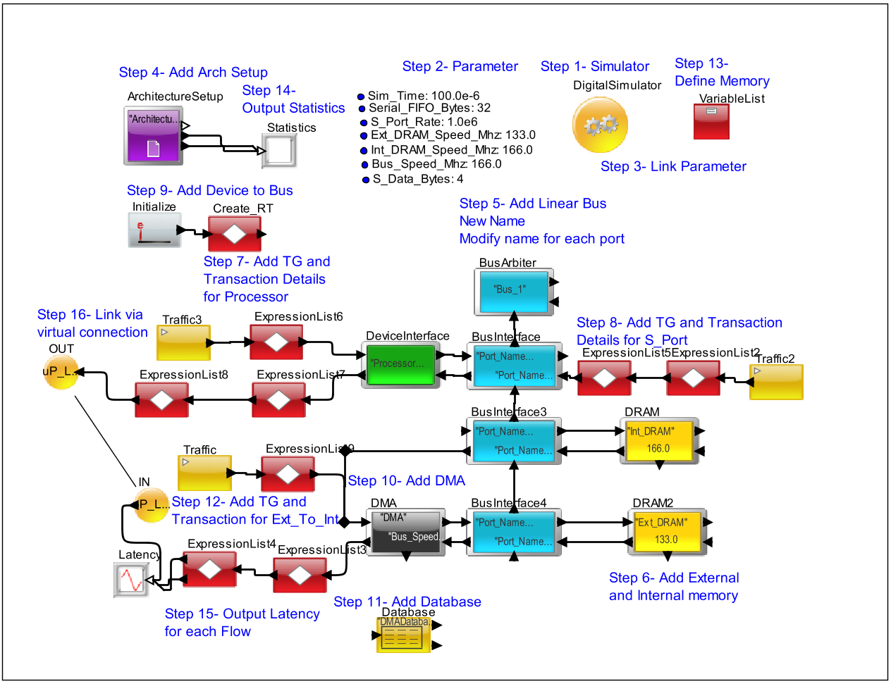
Figure 3. System Architecture Model
There are three data flows:
- One DMA channel moving from external to internal memory.
- One DMA channel moving from the serial port to internal memory.
- Processor reading from external memory.
DMA
- Processes bursts (8 reads, then 8 writes)
- Configurable overhead cycles per burst
- 2 logical channels
- Only 1 bus interface
- Higher priority channel can interrupt the lower priority channel between bursts only
Device Interface
- Use Device Interface block to define the name of the source
Serial Port
- Configurable FIFO depth and configurable frequency of receiving data.
- Trigger the DMA when the FIFO reaches a certain depth.
Memory
- Internal and external memory need configurable latency.
- Initial access has different access from subsequent beats of a burst.
Processor
- Generates random accesses in bursts of 32 Bytes.
Bus
- 32 bits wide
- 32 bytes are transferred in one burst
Other Details:
- A transfer as a read and a write.
- To move data from external memory to internal memory, the DMA reads from external memory and writes to internal memory.
- Likewise, to move data from
the serial port to internal memory, DMA reads from the serial port fifo
and writes to internal memory.
- The higher priority channel is the serial port channel. The lower priority channel is the external memory channel.
Step-by-Step Instructions
- Instantiate the Digital Simulator block. Select the digitalDomainOnly option to use the high-speed version.
- Add parameters. In
this case, the parameters are the Simulation Time; Serial port
frequency and FIFO depth; SRAM, DRAM and Bus speed; and Serial Data
Bytes size.
Sim_Time
:
100.0E-6
Serial_FIFO_Bytes : 32
S_Port_Rate
:
1.0E6
Ext_DRAM_Speed_Mhz : 133.0
Int_DRAM_Speed_Mhz : 166.0
Bus_Speed_Mhz : 166.0
S_Data_Bytes
: 4
- Link the Simulation Time with the Digital Simulator stopTime.
- Instantiate the Architecture_Setup block.
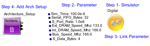
Figure 4. Arch_Setup
- Instantiate a
Linear Controller or BusArbiter and 3 Bus Interface / Linear Port
blocks below them. Configure it as shown in the figure below:
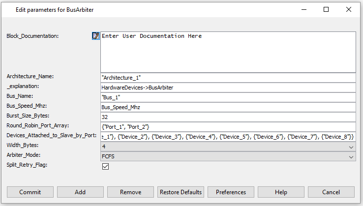
Figure 5. Linear_Bus
- Instantiate the External and Internal Memory (RAM blocks for both).
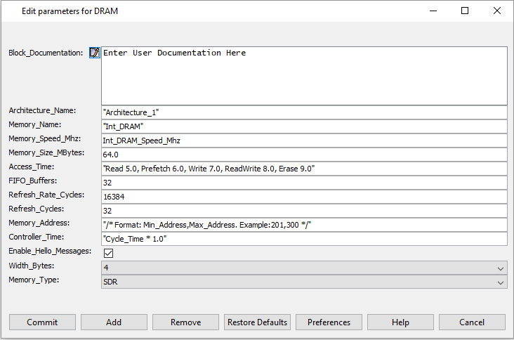
Figure 6. DRAM_Config
- Create Processor
first. Add the Transaction_Source to trigger the traffic and the
Processing block to provide the details of Source, Hop, Destination, and
Data Size.
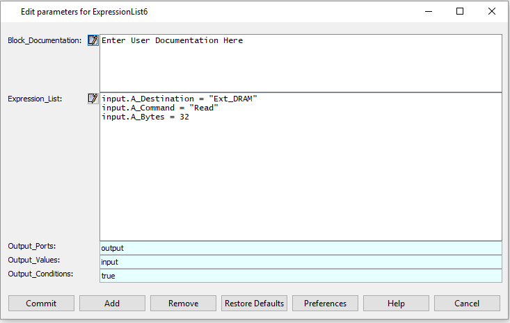
Figure 7. Parameters for Statement
- Use Device Interface to specify the source name as "Processor".
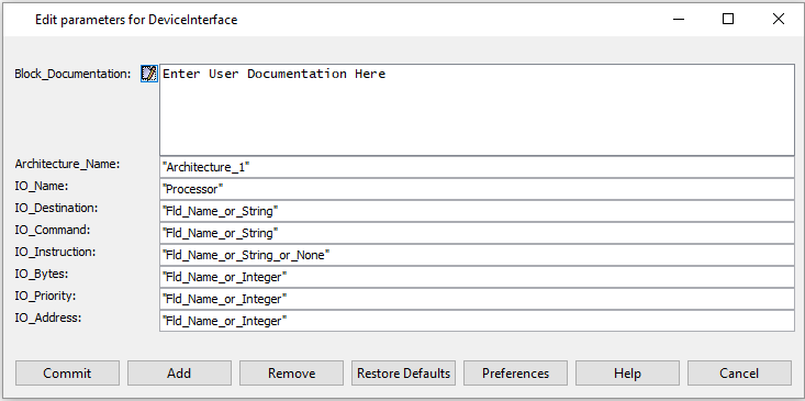
Figure 8. Parameters for Device Interface
- Connect them to the
Bus Interface.
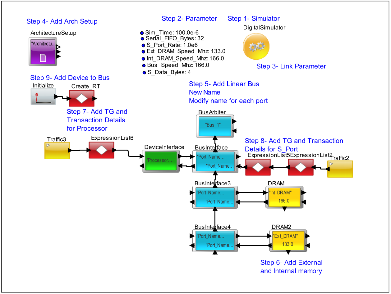
Figure 9. Before adding DMA
- Next instantiate and configure the DMA.
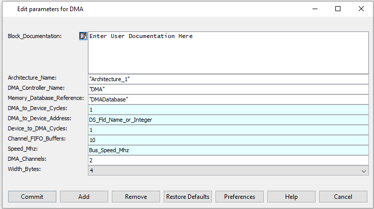
Figure 10. Parameters for DMA Controller
- Instantiate the
DMADatabase block. Specify the two flows. Notice that the
Ext-to-Int has two parts to the flow - one from the Ext DRAM to the DMA
and the second from the DMA to the Internal SRAM.
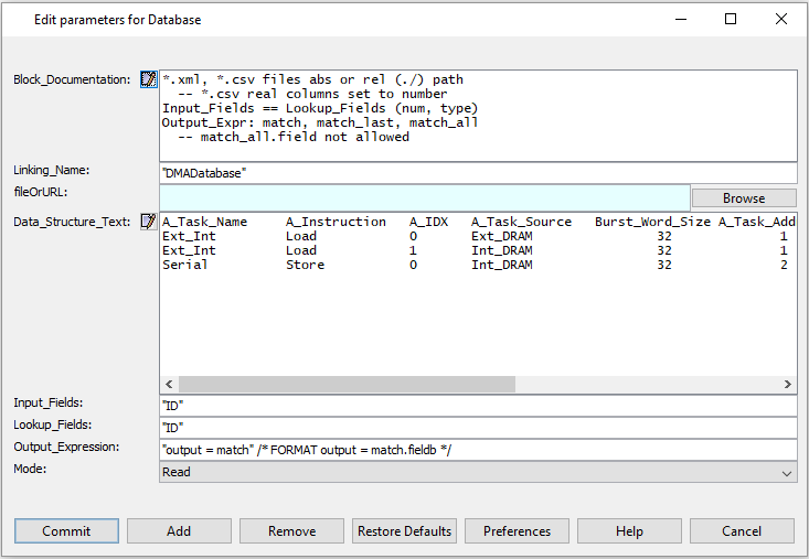
Figure 11. Parameters for Database Block
- Instantiate the
Traffic and the ExpressionList block to define the attributes to generate
the transactions for the Ext_to_Int transfer.
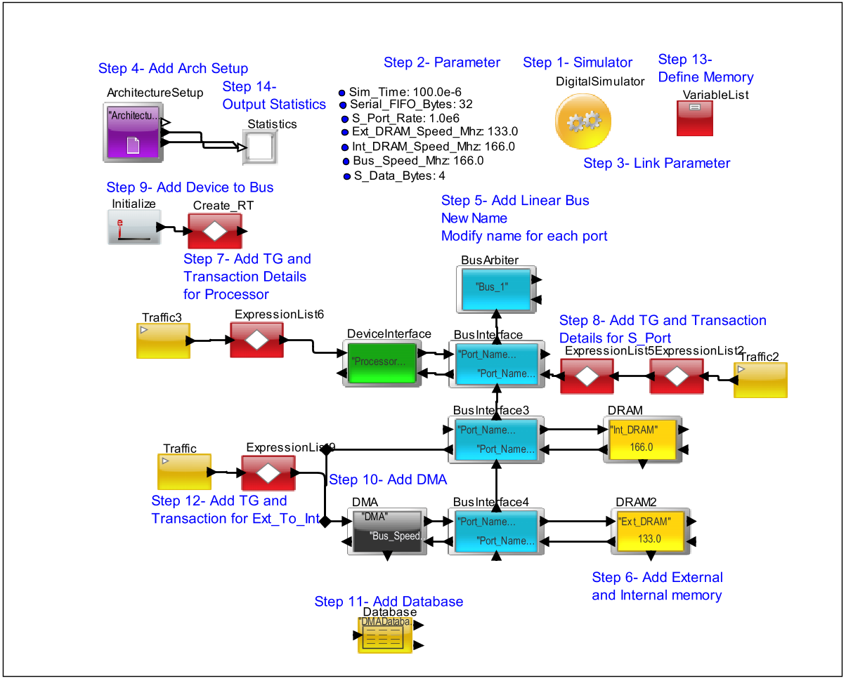
Figure 12. DMA_Next
- Initialize a memory to store the current FIFO depth for the Serial Port.
- Attach a
Text_Display block to the stats and util output of the
Architecture_Setup block. Also, configure the Trigger input to the
DMA for returning the acknowledge message.
- Connect the two DMA flows and the Processor flows to the Latency processing and TimeDataPlotter for displaying the Latency.
Figure 13. Full SRC
- Use the OUT + IN block to connect the Processor output to the Latency plotter.
Execution
- Click on the "GO" button to start the simulation.
- Make sure you get an output on the Text_Display.
Notes
- Compare the utilization of the different devices in the Text window.
- Also, notice the delays for
the high priority and low priority transaction. Vary the priorities and
measure the resulting performance.
- Observe the bus buffer occupancy to see if the data is overflowing.
- How is the priority handled between the processor, Serial Port and Ext_to_Int?
Hint: The bus reorders the
transactions based on priority.