Creating a Basic Architecture Model
The models are located in $VS/doc/Training_Material/Tutorial/Architecture_Exploration/Creating_Basic_System/.
This model demonstrates the
use of the Hardware Architecture Library in VisualSim. This session
combines the basic building blocks and the associated infrastructure
overhead.
Use this series of tutorials to understand how to connect and
configure the blocks in a system model.
Part 1: Construct a Processor model and execution instructions
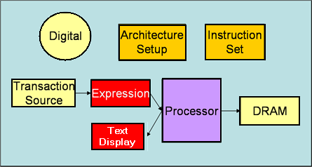
Figure 1 is a block diagram of the Basic Architecture Model.

Figure 1: Block Diagram of the Basic Architecture Model
Figure 2 is a VisualSim model of the Basic Architecture.

Figure 2: VisualSim Model of the Basic Architecture
Sl No |
Library Block |
Description |
1 |
Digital
|
This Simulator is used to model protocols, hardware, and mapping of behavior to architecture. This simulator is used when the model is being triggered as an event or based on time. The Digital Simulator implements the discrete-event Model of Computation (MoC). This Simulator maintains a notion of current time, and processes events chronologically in this time. Click here for detailed description & examples. |
2 |
Traffic
|
Traffic
block outputs a new Data Structure (DS) at time intervals specified by
the "Time_Distribution" setting. A Data Structure is a transaction
containing a list of Field Names + Values. |
3 |
ExpressionList
|
The ExpressionList blocks execute a sequence of expressions in order. The expressions can use the data on all the Input ports, Memories (Global and Local), Parameters, Numerical values, and String Constants. |
4 |
Text_Display
|
Display the values arriving on the input port in a text display dialog. This block buffers the display data and updates the screen after the buffer is full. Click here for detailed description and examples. |
5 |
Architecture Setup
Hardware Setup > Architecture_Setup |
This block handles all the address mapping, routing, plotting, statistics, and debugging for the Hardware Modeling components. |
6 |
Processor
|
The
Processor block is used to model variations of commercial and
proprietary processors. The goal of the block is to get accurate
timing, data flow, throughput, and power computation of the processor. |
7 |
Instruction Set
|
The Instruction_Set block can be used to create instruction references for the Processor. |
8 |
RAM
|
This
block combines the operation of a basic memory controller (delay
function) and the memory array. The block handles pre-fetch, read,
write, refresh, and controller operations. The block can be interfaced
to any Bus or Memory Controller.
Click here for detailed description and examples.
|