Adding a Bus
This section focuses on adding a bus to the VisualSim model.

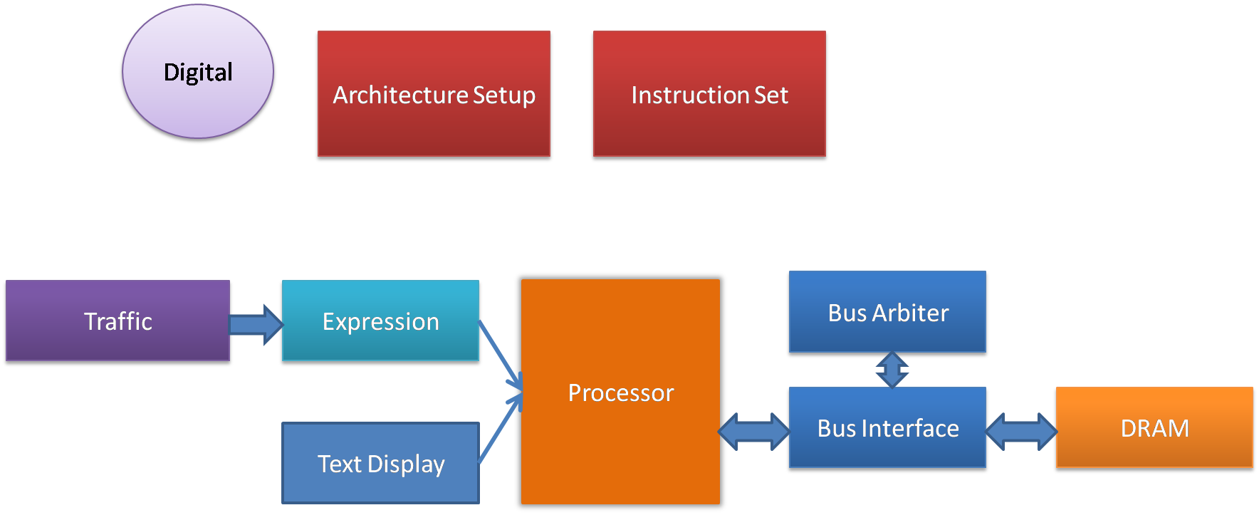
Figure 1: Enhancing the Basic VisualSim model with a BusArbiter
List of Additional Blocks
Sl No
|
Library Block
|
Description
|
1
|
BusArbiter

Hardware_Devices > Bus Arbiter
|
The Linear_Controller block is the Arbiter for a Linear Bus. The Linear bus is a shared bus topology with an arbiter.
Click here for detailed description & examples.
|
2
|
BusInterface

Hardware_Devices > BusInterface
|
The
Linear_Port block is used to connect the devices to the
Linear_Controller Bus. The block has a queue for each port.
The incoming transactions are queued and the head of the queue is sent
to the Controller Queue.
Click here for detailed description & examples.
|
Model Construction
- Disconnect the DRAM.
- Place the BusInterface and the BusArbiter one above the other.
- Connect the left side of the BusInterface to the Processor and the right-side to the DRAM.
Execution
Re-run the simulation and review the results.
Notes
- What is the difference between the Port and Controller?
- What is the significance of the Port names and Bus name in the BusInterface block? Do they have to be unique?
- If the devices are connected to a single BusInterface block, are they considered to be a direct connection?
Hint: No, it just means that they
are connected to the same shared bus.
- What is the purpose of the BusArbiter vs. the BusInterface?
Hint: The port has a queue for
the connected device. The BusArbiter provides the arbitration.
- Advanced topic - How do I
modify the Bus arbitration algorithm used? Use the in/out ports
on the right-side of the BusArbiter block.
