Switch Bus Analysis
Tutorial Goals
The following is a summary of the concepts you will learn in this session.
- Define routing flows.
- Use SystemResource blocks to model links.
- Measure system throughput.
Target
Bus architectures are developed as a proprietary
technology or evolved from a standard. Examples of buses include
PCIe, AXI and Hypertransport. Typical migration from one
technology to another is to
improve bus throughput and reduce bus latency. For example, new
generation microprocessor
and memory speeds outpaces throughput and latency ofolder bus design such as PCI.
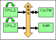
This lab focuses on building a switch-based bus in VisualSim to
evaluate overall throughput and latency for a single four port switch
configuration.

Figure 1: Block Diagram of the Switched Bus System
VisualSim Tutorial Model Location
Open this model in VisualSim from the following location:
File > Open File $VS/doc/Training_Material/Tutorial/WebHelp/Tutorial/Performance_Modeling/Bus_Lab.xml
Model Objectives
- Assume each device
connected to the Bus to have zero processing time. The important design
considerations are the forward and reverse links. Create each forward
and reverse link with a separate Mapper. We use a half-duplex link. For
this, the two mappers need to be mapped to a single SystemResource.
- Manipulate the 'Task_Class' Data Structure Fields, using the VisualSim Processing block.
- Traffic to generate link traffic.
- Processing to modify 'Task_Class' fields. Which fields would be important for the link processing-time and priority?
- Exposure to the Hierarchical-layered model.
- The devices and switches are built as Hierarchical blocks.
- Use virtual connections (IN and OUT) to perform dynamic-mapping of DS between the switch and the device.
- Determine if the Advanced Bus Architecture can support 1.5 GB/sec bandwidth.
- Each individual Bus Link can support 1.0 GB/sec (max).
- The Bus Switch can support 4.0 GB/sec (max).
Blocks Used
Sl No
|
Library Block
|
Description
|
1
|
Digital Simulator

ModelSetup > Digital
|
This
Simulator is used to model protocols, hardware and mapping of behavior
to architecture. This simulator is used when the model is being
triggered as an event or based on time. The Digital Simulator
implements the discrete-event Model of Computation (MoC). This
Simulator maintains a notion of current time, and processes events
chronologically in this time.
|
2
|
Traffic Sequence

Full Library > Source > Traffic > Traffic_Sequence
|
This
block is used to generate a sequence of data structures. Each line of
the file or Window is a data structure. The sequence can be modulated
by using the trigger port, Time and/or the Probability fields.
|
3
|
Processing

Behavior --> ExpressionList
|
The
Decision/Expression List blocks executes a sequence of expressions in
order. The default block contains one input and one output. The user
can add multiple input and output ports.
|
4
|
Mapper

Mappers > Mapper
|
This
block works with the separation of the behavior and architecture
methodology. In this methodology, the mapper block is placed in
behavior flow at every location where a timed resources is
required.
|
5
|
IN

Behavior > IN
|
This
block accepts incoming Data Structures or tokens from any
OUT/MUX/uEngine/Virtual_Machine blocks and sends a value on the output
port. The single parameter called Destination_Name is composed of two
parts - the name and the value to be output, separated by ".".
|
6
|
OUT

Behavior > OUT
|
The
OUT block accepts Data Structures or token arriving on the input port
and transmits it as a virtual connection to IN, MUX, NODE, Virtual
Machine, and uEngine.
|
7
|
Text_Display

Result > Text_Display
|
Display
the values arriving on the input port in a text display dialog. This
block buffers the display data and updates the screen after the buffer
is full.
|
8
|
xTime_yData_Plotter

Result > TimeDataPlotter
|
This
block plots the incoming data on the Y-Axis against the current
simulation time on the X-axis. Every wire connected to this block input
is considered a separate dataset and plotted separately.
|
9
|
SystemResource_Extend

Resources > SystemResource_Extend
|
This
block forms the architecture part of the behavior and architecture
separation methodology. In this methodology, the data structures
are transfered along the behavior flow.
|
10
|
SystemResource

Resources > SystemResource
|
This
block is a timed resource that combines a single input queue and a
processing (server) resource. A timed resource consumes units of
time to emulate the processing delay across a entity.
|
11
|
SystemResource_Done

Resources > SystemResource_Done
|
The
Scheduler_Release block is used to release the appropriate Scheduler_HW
block by signaling the completion of an external task.
|
12
|
Script

Behavior > Script
|
This
block implements the VisualSim Script language. This language
combines standard programming constructs with the RegEx functions and
is fully integrated with the graphical editor.
|
13
|
ResourceStatistics

Result->ResourceStatistics
|
This
is a pre-built block to place in a model to output or reset the
statistics for all the SystemResource, Quantity-Shared , Channel, Channel_N, Server and Queue in the model.
|
Block Diagram

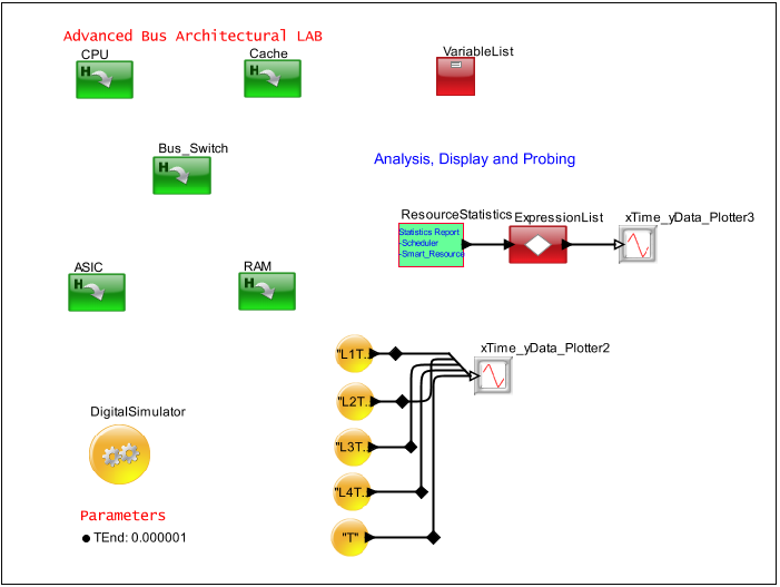
Figure 2. Shared Bus Analysis
Concept to Model Specification
Let us analyze the concept to model specification by the following questions.
- What blocks are required to define the Bus Switch function?
- How can the SystemResource/Mapper blocks be combined with virtual connections?
- Does this hierarchical block need "exported" parameters?
- Assume Bus Switch Capacity = 4.0 GB/sec
- What will the Bus Link function look like in terms of Mapper/SystemResource and Processing?
- Assume a full Duplex link for incoming and outgoing packets.
- Assume the Traffic Generator consists of a Transaction_Source (Fixed) + Processing.
- Does this hierarchical block need "exported" parameters to the next higher level?
- Assume a Link Capacity of 1.0 GB/sec
- Assume the following traffic profiles for a total of 1.5 GB/sec.
- CPU --> Cache 0.7 GB/sec
- Cache --> RAM 0.3 GB/sec
- ASIC --> RAM 0.5 GB/sec
- Add the
ResourceStatistics and add the list of SystemResource to the model. Now
connect the output to a Text_Display. This shows the statistics
for each of the individual devices.
- Add a Decision block to customize the output bandwidth utilization.
Model Considerations
- How to address different Bus Links, using virtual connection blocks? Consider the notion of routing using names?
Performance Model
Follow this procedure to design a performance model.
- Add 'TimeDataPlotter' to observer bus transactions of all four Bus Links and Bus Switch.
Hint:
Use unique 'Task_Number' in 'Task_Class' Data Structure for each
device. Send the plot output from each SystemResource
to TimeDataPlotter.
- Add blocks to observe the total Bus Link GB/sec in a second TimeDataPlotter.
Hint:
Accumulate Bus Link Bytes and divide by the simulation time for a
single sample, or create batch Bus Link GB/sec (10 samples).
- Comment on the observed Performance Model outputs.
- Do the results look reasonable? Is the model performing as planned?
- What happens if the Traffic uses another traffic distribution such as the uniform distribution?

