Can Bus Model
Block Diagram
The CAN Controller contains Transmit and Receive objects. The CAN Bus helps us to share the data between CAN Controllers. The CAN Controller1 starts transmitting the data from their Transmit object through a single wire called CAN Bus for every 1 msec. The Receiving object of the CAN Controller2 has a Queue. This model explains the performance evaluation of the simple CAN Bus Model and derives the step-by-step approach of developing CAN Bus Model as shown below.
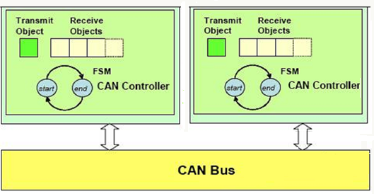
Figure 1: CAN Bus Block Diagram (Source: Paolo Giusto, General Motors)
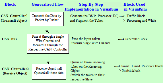
Figure 2: CAN Bus Model
To construct the model, we need to set the simulator (Digital), define the parameters and describing the model flow by adding blocks. The Traffic block sends out the 'Processor_DS' data structure based on the parameters Input_Rate1(Device1) and Input_Rate2 (Device2) using fixed distribution. The Expression_LIst block that follows the Traffic block sets the A_Bytes, A_Destination, A_Source, A_Priority, and a few other fields. CAN_Controller contains a transmit object and receive objects. The Token is passed from the Transmit Object through the single wire called CAN_Bus to the Receiving Object of another CAN_Controller. Receiving Object need to have a receive queue that gets messages every 1.0 msec.
A fully assembled model must look as below. You can also compare your model with the following model:
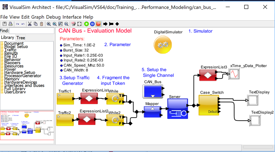
Figure 3: CAN Bus Model
The construction of the above model is described below.
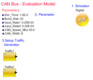
Figure 4: CAN Bus Evaluation Model-Step 1
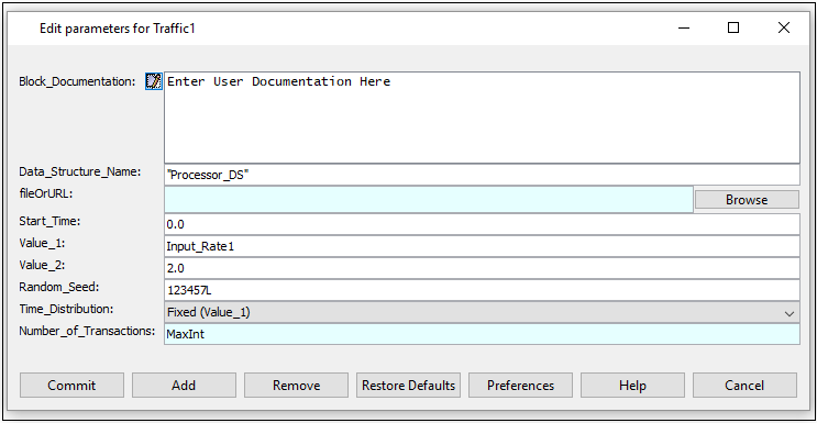
Figure 5: Parameters for Master 1
The following diagram shows the implementation of fragmentation in the transmit object using the While Block:
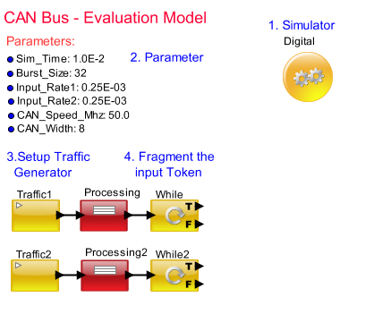
Figure 6: CAN Bus Evaluation Model-Step 2
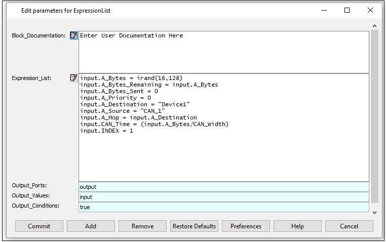
Figure 7: Parameters for Expr Script
For example, let us consider A_Bytes = 100, Burst_Size = 64.
Then, First Fragment=> (A_Bytes = 100, A_Bytes_Remaining = 36, A_Bytes_Sent = 64).
Second Fragment => (A_Bytes = 100, A_Bytes_Remaining = 0, A_Bytes_Sent = 36).
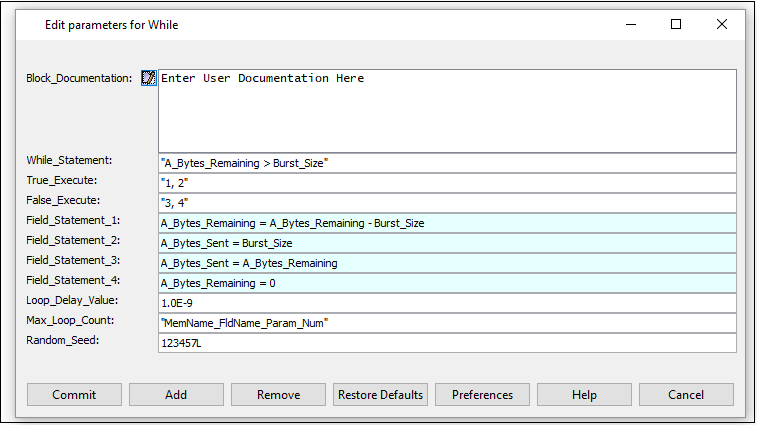
Figure 8: Parameters for Expr Script
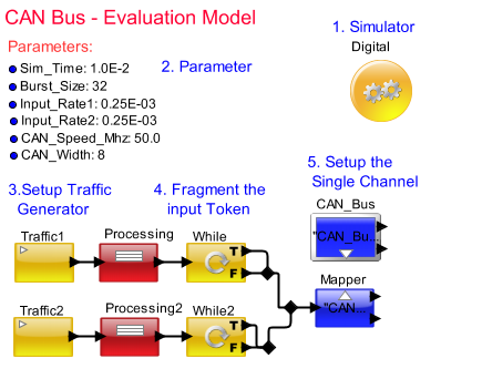
Figure 9: CAN Bus Evaluation Model-Step 3
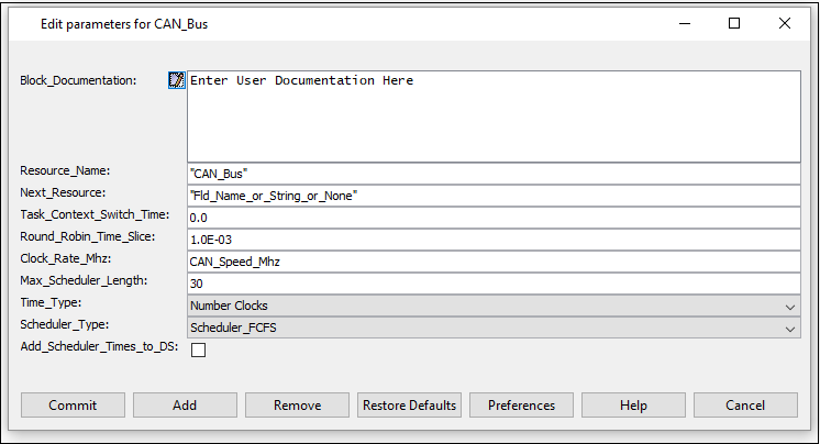
Figure 10: Parameters For Channel
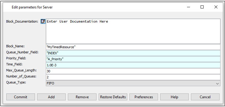
Figure12. Parameters for Server
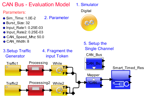
Figure 13. CAN Bus Evaluation Model-Step 4
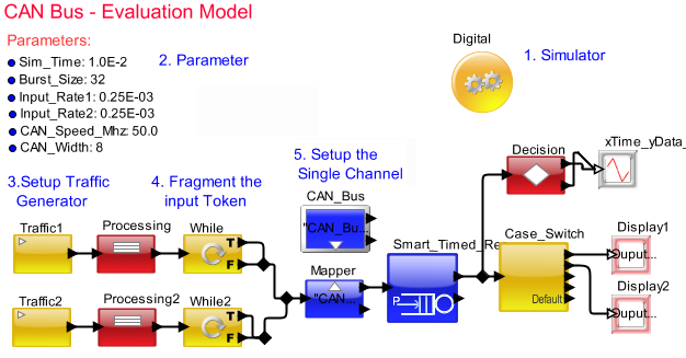
Figure 11: CAN Bus Evaluation Model-Step 5
Using the Listen-to-Port, we can find the token transaction with respect to the timing and we can debug the output.

Figure14. Listen to Port
Sample Output of the Mapper Listen-to-Port is as follows:
OUTPUT AT TIME ------ 40.30 ns ------
{A_Addr_Ctrl_Flag = true,
A_Address_Max = 100,
A_Address_Min = 1,
A_Branch = false,
A_Bytes = 19,
A_Bytes_Remaining = 0,
A_Bytes_Sent = 19,
A_Command = "Read",
A_Data = "MyData",
A_Destination = "Device1",
A_First_Word = true,
A_Hop = "Device1",
A_IDX = 0,
A_IDY = 0,
A_Instruction = {"ADD", "ADD"}
A_Instruction_Reorder = {1}
A_Interrupt = false,
A_Prefetch = false,
A_Priority = 0,
A_Proc_Return = -1,
A_Protocol_State = "MyState",
A_Return = -1,
A_Source = "CAN_1",
A_Status = "Status",
A_Task_Address = 1,
A_Task_Flag = false,
A_Task_ID = 0L,
A_Task_Name = "Name",
A_Task_Source = "Src",
A_Time = 0.0,
A_Variables = 16,
BLOCK = "Traffic1",
CAN_Time = 2,
DELTA = 0.0,
DS_NAME = "Processor_DS",
ID = 1,
INDEX = 1,
TIME = 1.0E-10}
OUTPUT AT TIME ------ 100.30 ns ------
{A_Addr_Ctrl_Flag = true,
A_Address_Max = 100,
A_Address_Min = 1,
A_Branch = false,
A_Bytes = 30,
A_Bytes_Remaining = 0,
A_Bytes_Sent = 30,
A_Command = "Read",
A_Data = "MyData",
A_Destination = "Device2",
A_First_Word = true,
A_Hop = "Device2",
A_IDX = 0,
A_IDY = 0,
A_Instruction = {"ADD", "ADD"}
A_Instruction_Reorder = {1}
A_Interrupt = false,
A_Prefetch = false,
A_Priority = 0,
A_Proc_Return = -1,
A_Protocol_State = "MyState",
A_Return = -1,
A_Source = "CAN_2",
A_Status = "Status",
A_Task_Address = 1,
A_Task_Flag = false,
A_Task_ID = 0L,
A_Task_Name = "Name",
A_Task_Source = "Src",
A_Time = 0.0,
A_Variables = 16,
BLOCK = "Traffic2",
CAN_Time = 3,
DELTA = 0.0,
DS_NAME = "Processor_DS",
ID = 1,
INDEX = 2,
TIME = 1.0E-10}
Using the Listen-to-Block, we can find the functionality of the block with respect to its timing and functionality.

Figure15. Listen to Block
Sample Output of the Mapper Listen to Block are as follows:
NEW TASK (1001) TNow: 3.0E-10 Parent: Mapper Data Structure:
{A_Addr_Ctrl_Flag = true,
A_Address_Max = 100,
A_Address_Min = 1,
A_Branch = false,
A_Bytes = 73,
A_Bytes_Remaining = 41,
A_Bytes_Sent = 32,
A_Command = "Read",
A_Data = "MyData",
A_Destination = "Device1",
A_First_Word = true,
A_Hop = "Device1",
A_IDX = 0,
A_IDY = 0,
A_Instruction = {"ADD", "ADD"},
A_Instruction_Reorder = {1},
A_Interrupt = false,
A_Prefetch = false,
A_Priority = 0,
A_Proc_Return = -1,
A_Protocol_State = "MyState",
A_Return = -1,
A_Source = "CAN_1",
A_Status = "Status",
A_Task_Address = 1,
A_Task_Flag = false,
A_Task_ID = 0L,
A_Task_Name = "Name",
A_Task_Source = "Src",
A_Time = 0.0,
A_Variables = 16,
BLOCK = "Traffic1",
CAN_Time = 9,
DELTA = 0.0,
DS_NAME = "Processor_DS",
ID = 1,
INDEX = 1,
TIME = 1.0E-10}
Next Name: CAN_Bus Task_Name: Name
SEND TASK (1001) TNow: 3.0E-10 Parent: Mapper
Called postfire()
NEW TASK (1002) TNow: 3.0E-10 Parent: Mapper Data Structure:
{A_Addr_Ctrl_Flag = true,
A_Address_Max = 100,
A_Address_Min = 1,
A_Branch = false,
A_Bytes = 81,
A_Bytes_Remaining = 49,
A_Bytes_Sent = 32,
A_Command = "Read",
A_Data = "MyData",
A_Destination = "Device2",
A_First_Word = true,
A_Hop = "Device2",
A_IDX = 0,
A_IDY = 0,
A_Instruction = {"ADD", "ADD"},
A_Instruction_Reorder = {1},
A_Interrupt = false,
A_Prefetch = false,
A_Priority = 0,
A_Proc_Return = -1,
A_Protocol_State = "MyState",
A_Return = -1,
A_Source = "CAN_2",
A_Status = "Status",
A_Task_Address = 1,
A_Task_Flag = false,
A_Task_ID = 0L,
A_Task_Name = "Name",
A_Task_Source = "Src",
A_Time = 0.0,
A_Variables = 16,
BLOCK = "Traffic2",
CAN_Time = 10,
DELTA = 0.0,
DS_NAME = "Processor_DS",
ID = 1,
INDEX = 2,
TIME = 1.0E-10}
Next Name: CAN_Bus Task_Name: Name
SEND TASK (1002) TNow: 3.0E-10 Parent: Mapper