HardwareDevices / BusInterface
Block Name: BusInterface
Code File Location: VisualSim/actor/lib/bus/Linear_Port
Table of Content
Description
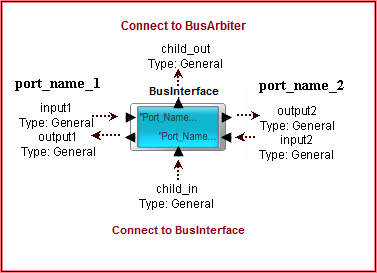
The BusInterface block is used to connect the devices to the BusArbiter. The block has a queue for each port. The incoming transactions are queued and the head of the queue is sent to the Controller Queue. When the transaction has been sent out, the current head of the Queue is sent to the arbiter. The two ports of this block are completely independent. Both ports can be attached to a Master or Slave devices. Both the input and output connections for each device must be attached. Otherwise the Routing Table will not be updated. The connection information of the device to the port and the communication between the devices and the rest of the topology is maintained in the Architecture_Setup block. The port queue is a priority queue and will reorder based on the priority of the incoming transaction. The priority is maintained in the A_Priority field. The Length of the queue are defined by the parameter called FIFO_Length. When the Queue is full, a exception is triggered and the simulation is terminated. No statistics are generated for this Queue. The flow of the Data Structure is from Input Port -> Controller -> Output Port.

Connections
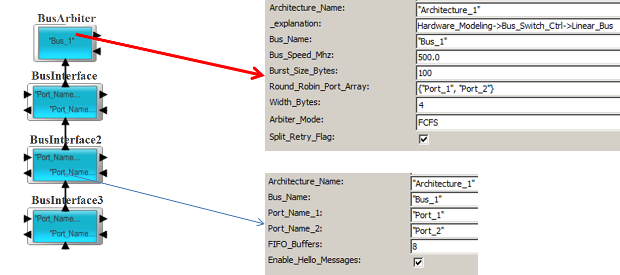
The BusInterface block is used in conjunction with the BusArbiter. In all cases, the block is used to connect devices to the Shared Bus topology. The blocks are linked serially with the Controller being at the top. All the BusInterface are connected in serial order. Refer to the demonstration examples for Read and Write.

The devices connected to the BusInterface can be a Processor, DMA, Memory Controller, Cache, DRAM, and custom device. To connect the custom device, use the Hardware->Core_Architecture->DeviceInterface block at the BusInterface interface. To use the DeviceInterface block with the left port, make sure to select block->Right-click->Appearance->Flip Ports Horizontally for the DeviceInterface block.

Demonstration Examples
To illustrate the usage, look at the following Examples in the BDE.
Delay Calculations
Write Delay: The delays in this block are the queuing at the BusInterface, one address/control cycle and the transfer of the data. The data transfer time is the A_Bytes/Bus_Speed. If there is a acknowledgement, then the delay is simply one cycle across the bus.
Read Delay:The delay in this block are the queuing at the BusInterface, followed by one address/control cycle. When the data returns from the Destination/Slave device, there is one address/control cycle, followed by the data transfer. The data transfer time is the A_Bytes/Bus_Speed.
Required Fields
The following fields are required by the Linear Bus, including AHB bus mode. If any of these fields are missing in the data structure, an exception will be reported.
The standard Processor_DS data structure also contains these fields:
A_Source, A_Hop, A_Destination, A_Bytes, A_Bytes_Remaining, A_Bytes_Sent, A_Command, A_Task_Flag, A_Status, A_Prefetch and A_Interrupt.