HardwareDevices / BusArbiter
Block Name: BusArbiter
Code File Location: VisualSim/actor/lib/bus/Linear_Controller
Table of Content
Description
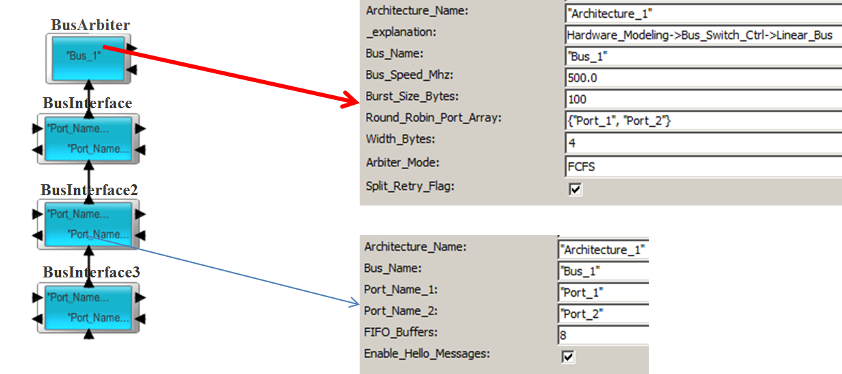
The BusArbiter block is the Arbiter for a Linear Bus. The Linear bus is a shared bus topology with a arbiter. The devices are connected to the ports of the BusInterface blocks. The connectivity betwene the BusInterface and Linear_Bus is shown below.

Examples of Buses created using this block include AMBA (AHB and APB) and PCI. Custom and proprietary shared bus topologies can also be created using this block.
The block parameters manages the operation of the block. The Architecture_Name is the name of the ArchitectureSetup block that maintains the routing, debugging and statistics information.
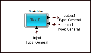
The Arbiter_Mode supports First Come-First Server, Round-Robin and Custom. The buffers on the input Linear Ports are priority-based and will reorder on the arrival of each new transaction. The first transaction in each port queue is sent to the Controller and scheduled at the Controller in the order of arrival. To customize the arbitration algorithm, the Arbiter_Mode is set to Custom and the logic is attached to the input1/output1 ports of this BusArbiter. The BusArbiter block has a single non-Priority Queue. All the BusInterface have equal access to the Arbiter and are equidistant. The content of this Queue can be accessed from the external Custom logic using the RegEx language. For more details about the usage, view the demo model and refer to the Advanced Modeling Documentation. The BusArbiter requires specific fields in the Data Structure to operate correctly. Refer to the demonstration examples in Pre-Built Models->Using Hardware Architecture Blocks->ReadBus.xml and WriteBus.xml.

Demonstration Examples
The devices connected to the Linear_port can be a Processor, DMA, Memory Controller, Cache, DRAM, and custom device. To connect the custom device, use the Hardware->Core_Architecture->I_O block at the Linear_Port interface.
To illustrate the usage, look at the following Examples in the BDE.
Delay Calculations
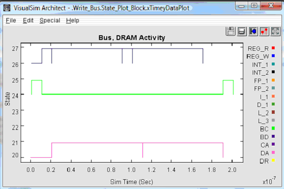
Write Delay: The delays in this block are the queuing at the BusInterface, one address/control cycle and the transfer of the data. The data transfer time is the A_Bytes/Bus_Speed. If there is a acknowledgement, then the delay is simply one cycle across the bus.
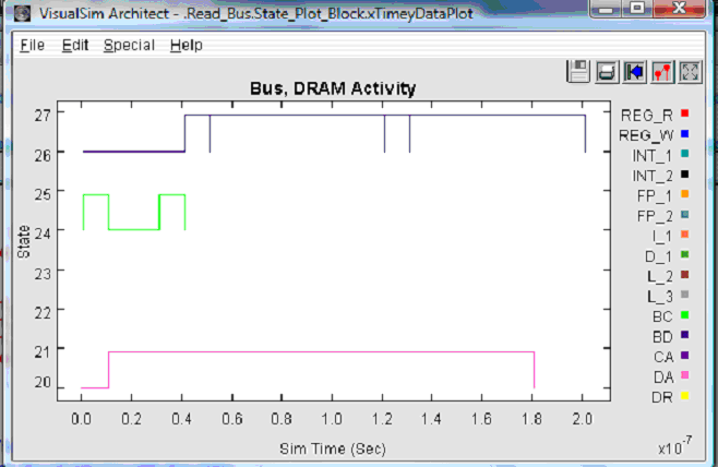
Read Delay:The delay in this block are the queuing at the Linear_Port, followed by one address/control cycle. When the data returns from the Destination/Slave device, there is one address/control cycle, followed by the data transfer. The data transfer time is the A_Bytes/Bus_Speed.
Required Fields
The following fields are required by the Linear Bus, including AHB bus mode. If any of these fields are missing in the data structure, an exception will be reported.
The standard Processor_DS data structure also contains these fields:
A_Source, A_Hop, A_Destination, A_Bytes, A_Bytes_Remaining, A_Bytes_Sent, A_Command, A_Task_Flag, A_Status, A_Prefetch and A_Interrupt.
Write Transactions- Master to Slave
A Write transaction proceeds as follows.
- The transaction Arrives from Master and is saved in the respective Port FIFO Buffer. The port buffer size is set to FIFO Buffer. The source is in the A_Source, destination is in A_Destination, transaction type is in A_Command (Read, Write, Prefetch, Erase etc.) and transaction size is A_Bytes. A_Bytes = A_Bytes_Remaining + A_Bytes must be true, else the transaction will be rejected.
- The incoming data structure is fragmented based on the Controller Burst_Size parameter. These fragments are stored in the port queue. The port queue must be sized based on number of expected fragments.
- Each Port sends the first transaction in the port queue to the BusArbiter. The port queue does not send the remaining fragments associated with the transaction. In the case of the Round-Robin, the head of each Queue is sent to the Controller in the order specified in the Round-Robin Port Array parameter.
- A single cycle address/control transaction (Write control) is transferred through the bus. The control signal delayed internally but the signal is not sent out of the bus.
- After this control cycle, the first fragment is sent out. Each burst fragment of the transaction is delayed internally and is not sent out of the port. The burst is a parameter of the Linear Controller block called Burst_Size_Bytes.
- The A_Source, A_Destination, A_Bytes and A_Command are not modified for the Read and Write output. For the Write, the A_Bytes_Remaining is decremented for each burst and the A_Bytes_Sent = Bus_Burst_Width.
- A_First_Word is a special field used in the Custom_Flow. The Processor uses this field to identify a unique transaction among the fragments.
- If
A_Task_Flag = true, the Slave will
send a response when all data has been written into the Slave block.

Figure 1. Timing Diagram – Write Transaction
The following table shows an example of a Write activity:
| List
of Fields |
Input from Master | Output
to Slave (Burst 1) |
Output to Slave (All other Bursts) |
| A_Bytes | Request Data Size | Value unchanged | Value unchanged |
| A_Bytes_Remaining | Request Data Size -Master Width | Request Data Size -Bus Burst Width | Request Data Size -2* Bus Burst Width |
| A_Bytes_Sent | Master Width | Bus Burst Width | Bus Burst Width |
| A_Destination | Final Destination | No Change | No Change |
| A_Source | Original Source | No Change | No Change |
| A_First_Word | TRUE | No Change | No Change |
| A_Interrupt (Opt.) | FALSE | No Change | No Change |
| A_Prefetch
(Opt.) |
FALSE | No Change | No Change |
| A_Status | Used internally by Linear Bus. Set to Slave port name | Set to Slave port name + Append "_" | Set to Slave port name + Append "_" |
| A_Hop | Slave side port name | Next Bus or Destination if direct connect | Next Bus or Destination if direct connect |
| A_Task_Flag | Don’t care | No Change | No Change |
| A_Command | Write | No Change | No Change |
Table 1. Write Activity
Write Response
- If A_Task_Flag= true, a write response will be sent back to the Master from the Slave.
- All rules pertaining to the transaction fields remain the same as the Write Transaction.
- When the response arrives at the Bus, it sent out immediately. Look at the Table 2 Output value.
The following table shows an example of a Write Response:
| List of Fields | Input from Slave | Output to Master |
| A_Bytes | Request Data Size | Value unchanged |
| A_Bytes_Remaining | Request Data Size | Request Size - Bus Width |
| A_Bytes_Sent | 0 | Bus Width |
| A_Destination | Final Destination | No Change |
| A_Source | Original Source | No Change |
| A_First_Word | TRUE | No Change |
| A_Interrupt (Opt.) | FALSE | No Change |
| A_Prefetch (Opt.) | FALSE | No Change |
| A_Status | This is used internally by the Linear Bus. This is set to Master port name | Append _ to_Name |
| A_Hop | Don’t Care | Next Bus or Destination if direct connect |
| A_Task_Flag | Don’t Care | Don’t Care |
| A_Command | Read. Can have any suffix | Unchanged |
Table 2. Write Response
Read Transaction
A Read transaction proceeds as follows.
- The transaction arrives from Master and is saved in the respective port FIFO Buffer. All ports have the same size buffer and are set to FIFO Buffer. The source is set in the A_Source, destination is provided in A_Destination, transaction type is set in A_Command (Read, Write, Prefetch, Erase etc.) and transaction size is A_Bytes. A_Bytes = A_Bytes_Remaining + A_Bytes_Sent must be true, else the transaction will be rejected.
- The Port informs the Bus Arbiter of the transaction. When the bus is available, the Controller selects a Port, based on the arbitration.
- When the transaction is accepted for transfer, the Data Structure is delayed by one cycle for the Address Control. Then the Data Structure is output. Output value is shown in table 3.
- The return data fragments are transferred to the master through the bus taking several cycles, depending on the bus width, burst size, bus speed, bytes transferred etc. The last word for each burst of the transaction is sent out.
Read Request Transaction:
The following table shows an example of a Read Request Transaction:
| List of Fields | Input from Master | Output to Slave |
| A_Bytes | Request Data Size | Value unchanged |
| A_Bytes_Remaining | Request Data Size- Master Width | Request Size - Bus Width |
| A_Bytes_Sent | 0 | Bus Width |
| A_Destination | Final Destination | No Change |
| A_Source | Original Source | No Change |
| A_First_Word | TRUE | No Change |
| A_Interrupt (Opt.) | FALSE | No Change |
| A_Prefetch (Opt.) | FALSE | No Change |
| A_Status | This is used internally by the Linear Bus. This is set to Slave port name | Append _ to_Name |
| A_Hop | Don’t Care | Next Bus or Destination if direct connect |
| A_Task_Flag | Don’t Care | Don’t Care |
| A_Command | Read. Can have any suffix | Unchanged |
Table 3. Read Request Transaction
Read Transaction- Response:
The following table shows an example of a Read Transaction- Response:
| List of Fields | Input from Slave | Output to Master (End of all Bursts) | Output to Master (All other Bursts |
| A_Bytes | Request Data Size | Value unchanged | Value unchanged |
| A_Bytes_Remaining | Request Data Size- Slave Width | Request
Data Size -Bus Burst Width |
Request Data Size -2* Bus Burst Width |
| A_Bytes_Sent | Slave Width | Bus Burst Width | Bus Burst Width |
| A_Destination | A_Source (Names flipped from Request. Can be an alternate destination also) | No Change | No Change |
| A_Source | A_Destination (Names flipped from above. Can be an alternate destination also.) | No Change | No Change |
| A_First_Word | TRUE | No Change | No Change |
| A_Interrupt (Opt.) | FALSE | No Change | No Change |
| A_Prefetch (Opt.) | FALSE | No Change | No Change |
| A_Status | Used internally by Linear Bus. Set to Slave port name. | Set to Master port name + Append "_" | Set to Master port name + Append "_" |
| A_Hop | Slave side port name | Next Bus or Destination if direct connect | Next Bus or Destination if direct connect |
| A_Task_Flag | Don’t Care | No Change | No Change |
| A_Command | Write | No Change | No Change |
Table 4. Read Transaction- Response

Figure 2. Timing Diagram – Read Transaction
Custom Arbitration Flow
- The transactions arrive at the ports. The Linear Bus does not distinguish between Master and Slave ports. All ports have a port Queue and the transactions are blocked until the head transaction has completed. The length of the port Queue is a parameter of the BusInterface block.
- All transactions are fragmented, according to the Burst size, and stored in the port Queue.
- The front transaction of each port is sent to the arbiter Queue. The arbiter Queue is in the Linear_Bus block. This block has input1 and output1 ports to handle the custom arbitration flow.
- The Arbiter logic is connected to the input1 and output1 ports. A copy of the first transaction in the Arbiter Queue, also called head of the queue is sent on output1 and triggers the custom flow.
Typical flow involves first getting the length of the arbiter Queue using the RegEx function.
Then loop through the arbiter Queue to examine each item, depending on the arbitration algorithm.
Next, determine which transaction fragment to transmit. The list of RegEx functions can be viewed by looking at Linear Bus Extensions portion of the RegEx.
- If a user sets a field called A_Addr_Ctrl_Flag = true, an address/control cycle is generated in the bus plot, when the address fragment is sent to Linear_Bus -> input1. Typically, this would be for the first fragment in a transaction.
- Next, the data fragment are by simply changing A_Addr_Ctrl_Flag = false, and removing the head of the queue and sending it to the Linear_Bus->input1.
- Users has control over the transmission of address/data fragments selected and their cycle timing.
- Users can also wait for an address or data fragment just issued in the custom flow, by ignoring new triggers, and looping until a device responds.
- In the Custom Mode, transactions can be sent out in any order and at any time.
Retry Operation
The RETRY response works only for Read operations. It currently does not support Write operations. It provides a mechanism for slaves to release the bus when they are unable to supply data for a transfer immediately. The mechanism allows the transfer to finish on the bus and therefore allow a higher-priority master to get access to the bus.
If the Core->Cache or DRAM is used, the block uses the getBlockStatus RegEx to determine the status. For any other Destination, the Bus will check the global memory called Destination Name + "_Status". If the value of the RegEx or this Global Memory is true, the normal transfer occurs. If the value is false, then the Bus will generate a Retry. When a Retry occurs, the arbiter will continue to use the normal priority scheme and therefore only masters having a higher priority will gain access to the bus.