
Multi-Channel DMA
Tutorial Goals
The following is a summary of the concepts you will learn in this session.
- Use Statistical SystemResource blocks to define the resources in a system.
- Use the channel blocks to define distributed activities.
- Manage the Cache/SDRAM usage information with VisualSim memory elements.
Target
In this section we focus
on the effect of using a shared DMA for memory access. The model has
multiple resources that consume time in the flow. There are some
devices with direct connections to the DMA and others are connected to
it via a Bus. This tutorial helps the user to understand the
TimedQueues and Channels, and the generation of latency plots.
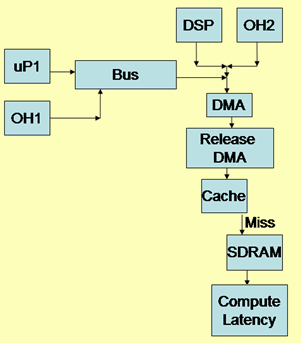
Figure 1: Block Diagram of the Multi-Channel DMA Design
VisualSim Tutorial Model Location
Open this model in VisualSim from the following location:
File->Open $VS/doc/Training_Material/Tutorial/WebHelp/Tutorial/Performance_Modeling/DMA_Exercise.xml
Model Objectives
- Identify the resources and the flows.
- What block should be used to model the DMA?
- What is the traffic generation schemes to be deployed?
- Make hit-and-miss decisions.
Blocks Used
- Traffic >Traffic
- Full Library > Defining Flow > Processing
- Behavior > Expression_List
- Behavior > IN
- Behavior > OUT
- Behavior > Fork
- Results > TextDisplay
- Results > TimeDataPlotter
- Full Library > Resource >Timed-Queue >TimedQueue
- Full Library > Resource > Channel and Pipeline >Channel
- Full Library > Resource > Channel and Pipeline > Channel_Release
Model Construction
- Parameters for the model are:
- µP1- Speed=500MHz, Data Size=24 bytes, ID="µP"
- DSP1- Speed=266MHz, Data Size=16 bytes, ID="DSP"
- OH1- Inter-arrival time between 100-200 µs, Data Size= 64 bytes, ID= "OH1"
- OH2- Inter-arrival time of 150 µs, Data Size= 8 bytes, ID= "OH2"
- DMA- packet size=64 bytes, buffer=32
- Bus- Speed=266MHz
- Cache- Speed=266MHz
- SDRAM- Speed=133MHz
- Model Variables: How do you include this in the model?
- DMA speed =< 266 MHz
- Number of DMA channels = 4-16
- Cache hit ratio = 0.7-0.9
- Simulation Output
- Plot the request latency from µP and DSP when accessing SDRAM.
- Print the complete
DS after the data has been accessed. In this case, assume all
transactions to be a Write. So, there is no return path.
- Analysis
- Is there a relation between the cache hit ratio and the miss latency?
- Which parameter (Cache hit ratio, DMA speed and DMA channels) has the biggest impact on the latency?
Construction Steps
The Construction of the above model in a step-by-step manner is described below.
- Open a new block diagram by selecting File > New > Block Diagram.
- Drag the Digital block (ModelSetup >
Digital) onto the block diagram. Make parameter "StopTime = 5.0e-6”
(user-defined value). Maintain the default for all other values.
- Setup the Parameter (ModelSetup > Parameter=) as shown below:
Bus_Speed
=
266
UP_Speed_Mhz = 500.0
DSP_Speed_Mhz = 266
SDRAM_Speed = 133
DMA_Speed
=
500
DMA_Packet_Size = 32
Cache_Speed
= 266
Cache_Hit_Ratio = 0.9
- Setup the Traffic using Traffic (Traffic >Traffic) for µP, DSP, OH1, and OH2.
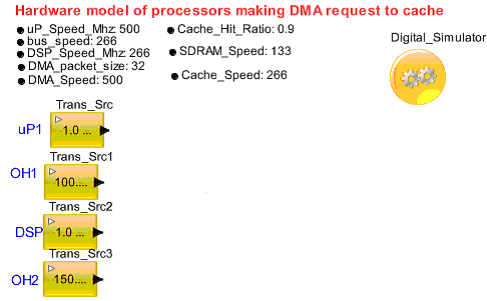
Figure 1. Traffic Generation
- Drag the Processing block from Full Library > Defining_Flow > Processing to
define the transaction Field (by double-clicking the block). Setup the
field values such as Source_Name, Transaction_Bytes, Hit_or _Miss, and
Timing Delay.
- µP1 and OH1

Figure 2. Parameter value for µP1 and OH1
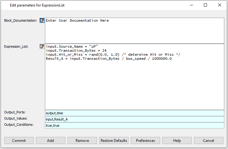
Figure 3. Assign the Field value for DSP and OH2
- Drag the TimedQueue
block (Ful Library > Resource > Timed-Queue > TimedQueue)
and pop-out the token according to the Transaction_Bytes /
bus_speed_Mhz.
- Setup the DMA block
(Full Library > Resource > Channel and Pipeline > Channel)
and the DMA Release block (Ful Library > Resource > Channel and
Pipeline > Channel_Release).
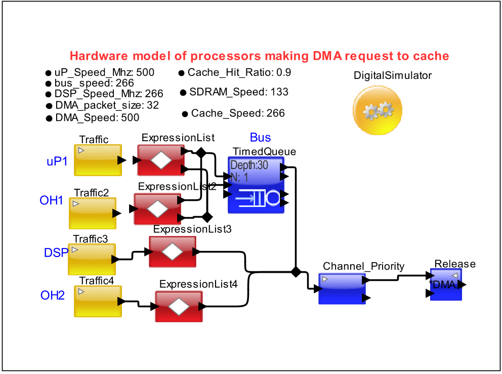
Figure 4. DMA Access
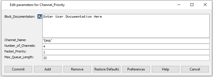
Figure 5. Channel Parameter Setup
- Pass the Token
through the Virtual Connection (Behavior > IN and Behavior
> OUT) to the Cache containing TimedQueue which triggers the
token according to the Transaction_Bytes / Cache_speed_Mhz.
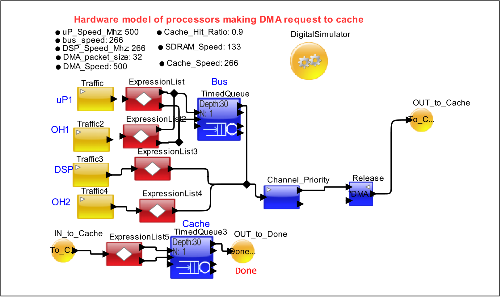
Figure 6. Cache Access
- Verify the Cache Hit or Miss using Decision block (Behavior > Expression_List).
If Cache Hit, display the output
If Cache Miss, access the SDRAM
Cache Hit or Miss Calculation:
Result_A = (input. Hit_or_Miss <= Cache_Hit_Ratio)?True: False
- In case of
Cache_Miss, pass the token into the SDRAM (TimedQueue) and Pop-out the
Token according to the Transaction_Bytes / SDRAM_speed_Mhz.
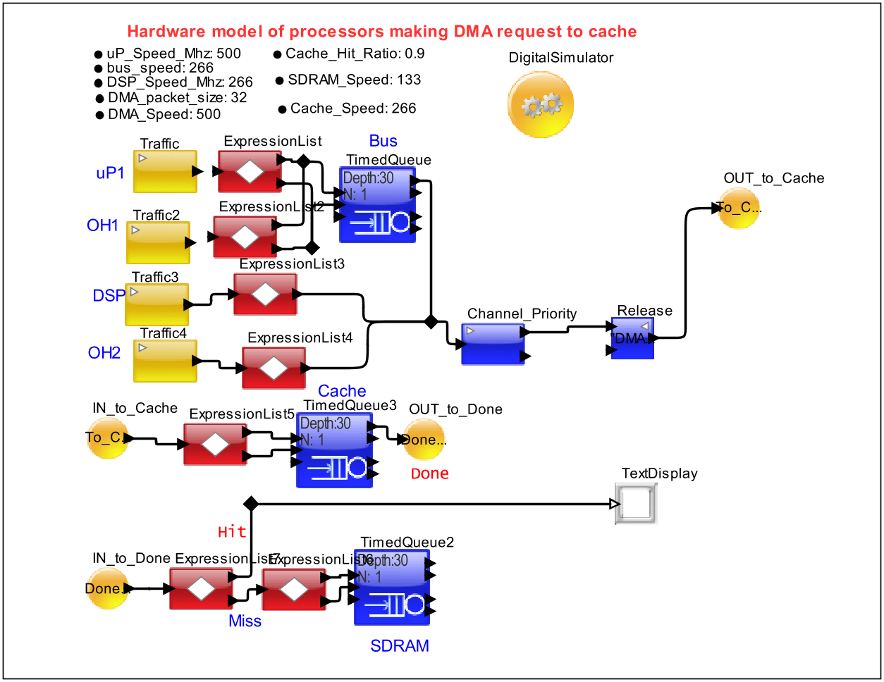
Figure 7. Cache Miss access the SDRAM
- Derive the latency for Cache_Miss (uP_Cache_Request_Latency, DSP_Cache_Request_Latency) and Cache_Hit and plot it.
uP_Cache_Request_Latency = TNow - input.TIME
DSP_Cache_Request_Latency = TNow - input.TIME
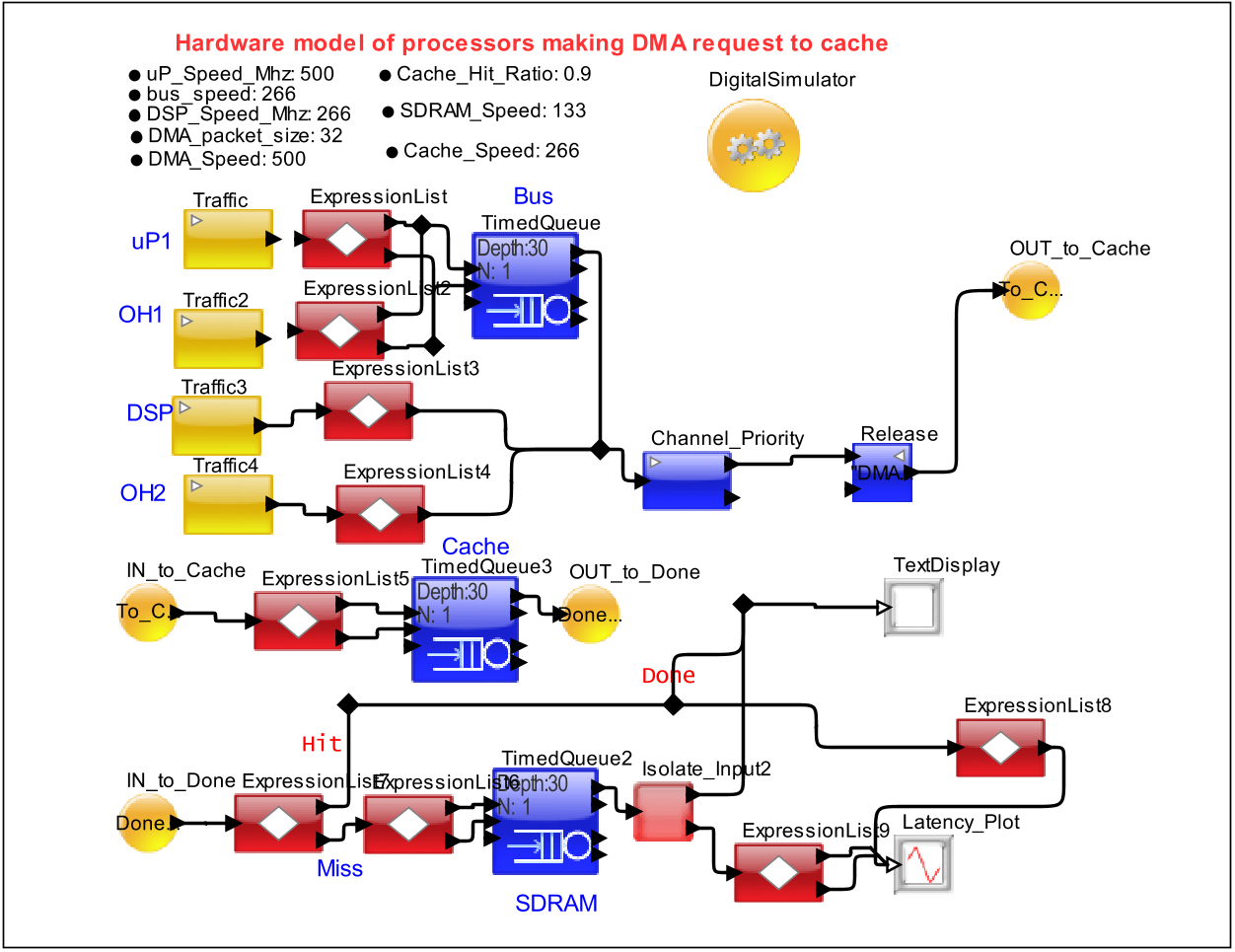
Figure 8. Multi Channel DMA Design


