Multiple demonstration system models are provided with documentation to guide a user to adopt VisualSim FireWire Library for conducting early system exploration of FireWire based system. Purpose of the following tutorial is to introduce VisualSim FireWire libraries and understand the basic rules that need to be followed during model construction.
Block diagram of a simple FireWire based system with single FireWire Root Node a Leaf Node is as below.

Figure 1.0: System Block Diagram
Here we have a single Leaf node
generating Isochronous or
Asynchronous transactions and it can be considered as a camera or an
audio
source connected to a Computing resource or a Root node. Root Node
generates a
special packet called “Clock Start” every 125.0us. Leaf node can
request for
Arbiter control by sending a Arbiter Request message across the network
to Root
node. As we have only one device connected to Root Node, Leaf Node always
wins the arbitration, else arbitration is granted based on first
come first
serve order.
After the Arbitration is granted for a Leaf node, leaf node can send a data packet per cycle. If the bandwidth is available, multiple packets can be transmitted. Modeling a FireWire System as shown in figure 1.0 using VisualSim requires FireWire Library package. FireWire Library package includes FireWire Node, to model Root/Branch/Leaf nodes; FireWire Link, to model connectivity medium between two nodes; FireWire Config, to define the network setup and Bandwidth allocation.
VisualSim model of the proposed system is shown below.
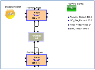
Figure 2.0 VisualSim Model
1. While constructing the Simulation model of a FireWire based system, we assume that the topology has been identified and self-identification process is complete. As this does not impact on total System performance, this process is left out.
2. Always Start providing Unique identifier for nodes from Leaf Nodes and move up the ladder. Always Leaf Nodes have the lowest identification numbers and Root nodes have the highest identification number.
3. User must determine if the transactions are Isochronous or Asynchronous based on the type of the device modeled using FireWire Node block.
4. Parameter called Root_Node with the name of Root node must be instantiated into the Block Diagram Editor.
To Construct a FireWire network model, there are four steps
1. Instantiate the FireWire Node, Link, and FireWire Config blocks
2. Configuration of FireWire Node and FireWire Config blocks based on design requirements.
3. Connect Nodes based on the Network Topology
4. Run Simulation and Analyze reports
1. Open a New Block Diagram Editor from File > New > Block Diagram Editor.
2. Instantiate Digital Simulator from the Library Menu Model Setup > Digital Simulator.
3. Instantiate Parameter from the Library menu Model Setup > Parameter. Rename the Parameter as “Sim_Time” and assign the value as 40.0e-4.
4. Double click the Digital Simulator and enter Sim_Time for stopTime Parameter.
1. Instantiate FireWire_Node from the Library pane Interfaces and Buses > FireWire > FireWire_Node.
Updating the parameter Node_Type to
Root transforms the FireWire Node block to behave as a root in the
network. As
this is a Root node, identifier for the node must be provided with
highest
identifier number. For "Root" Node, user can ignore parameters;
Arb_Req_Start_Time,
Destination_Node, Transfer_Type, Task_Size_Bytes, and
Arb_Req_Interarrival_Time.
Configure the Block as below.
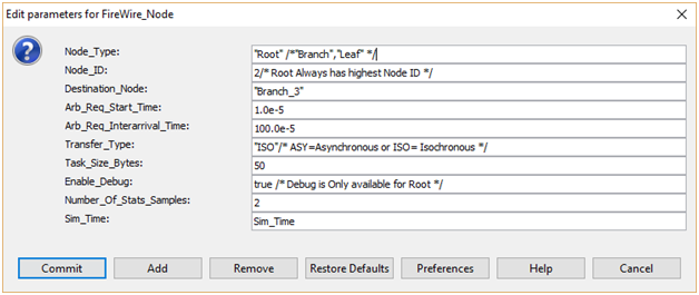
2. Instantiate one more FireWire_Node from the Library pane Interfaces and Buses > FireWire > FireWire_Node.
Updating
the parameter Node_Type to
Root transforms the FireWire Node block to behave as a root in the
network.
Node must be provided with a unique identifier and the root node must
be
provided with highest identifier number and Leaf Nodes have must
have
least identifier number. FireWire Node is provided with a facility to
generate
Isochronous or Asynchronous transfers, Parameter "Transfer_Type" must
be set to "ISO" for Isochronous and "ASY" for Asynchronous
transfers. Parameter "Arb_Req_Start_Time" tells Leaf/Branch node to
initiate Arbitration Request; Arb_Req_INterarrival_Time parameter
allows user
to set mean time to generate Arbitration Request.
In this example as we have only 2 nodes, destination node for Leaf_1 is
set to
Root_2. Arbitration Request message is generated every 100 us and
the
packet size of 1000 bytes is sent as an isochronous transfer.
Configure the Block as below
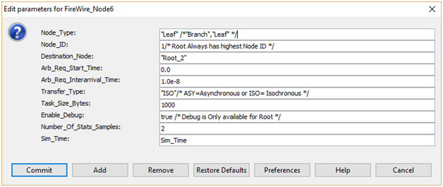
3. Instantiate FireWire_Link Node from the Library pane Interfaces and Buses > FireWire > FireWire_Link.
FireWire Link is a simple delay block that computes link delay based on the link type and distance between on e node to another. FireWire is available in wireless, fiber optic, and coaxial versions using the isochronous protocols.
4. Instantiate FireWire_Config Node from the Library pane Interfaces and Buses > FireWire > FireWire_Config.
FireWire Config block is responsible for maintaining routing information and Maximum Bytes per cycle for a selected Network Speed.
As we have just two nodes, routing table has a connection defining Leaf_1 to Root_2 and Root_2 to Leaf_1. Distance is considered as 10 meters, user can modify this parameter. The Link Leaf_1 to Root_2 is running at 400 Mbps and is mapped to the block Parameter. User can modify the network speed and ISO_BW_Percent during explorations.
Configure the block parameters as below.
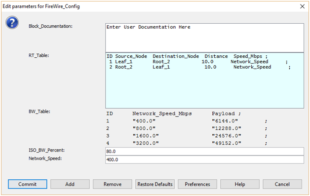
5. Connect Nodes as shown in figure below.
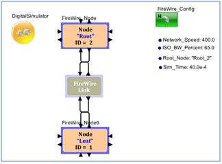
FireWire
Library blocks are preconfigured to generate various reports and debug
information. Configuring Enable_Debug parameter to “true” in Root node
generates the reports and statistics. Activity graph is generated to
debug
network behavior and it captures details such as Arbitration Request
arrival
time, Arbitration Grant time, and arrival data packet at Root Node for
both
Isochronous and Asynchronous transfers. Textual report on Network
Statistics
helps designer to understand the bandwidth for each link and source to
destination nodes. Debug messages are generated in textual format and
is saved
in the same directory where the model is located.
Activity Plot
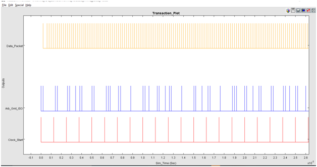
Activity plot provides time stamp details on when a Arbitration is granted for Isochronous transfers or Asynchronous transfers, time stamp for clock start packet and arrival of data packet at Root Node. This plot is useful to monitor the network behavior.
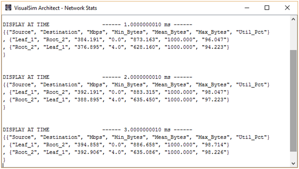
Network Statistics
Network Statistics shows that each link
connected to a node can capture the Mbps and min,
mean, stdev, and max of the link utilization. Network Statistics shown
below tells
us that the link Leaf_1 to Root_2 is having a bandwidth of 384.191 Mbps
and the
mean Bytes transferred across this link is 873 bytes while the maximum
Bytes
transferred across the link is 1000 Bytes. This also shows that the
Link
utilization is of 96.047%. This tells us the if the designer has to
consider
adding additional links to the network, care must be taken to make sure
that
the packets drop is avoided.
Debug Statistics
Debug Statistics provides information on when a Clock Start signal is sent to a node, Node that received Arbitration Grant message, details on active channel, and Available Bandwidth for Isochronous and Asynchronous Transfers. These debug messages help designers to understand System behavior and make sure that the activity across the network is free from errors.
1. VisualSim.kernel.util.IllegalActionException:
Problem performing RegEx Script Line (27) Result: {"none"}
Solution: This error appears when the parameter Network_Speed is set to speed apart from 100, 200, 400, 800, 1600, and 3200. Make sure that parameter Network_Speed is provided with one of the above six values.
2. VisualSim.kernel.util.IllegalActionException:
Problem performing RegEx Script Line (11) Result: {"Root_2"}
Solution: This error tells that the parameter Root_Node = “Root_2” (or the Name of the Root node in your case) is missing. Add a parameter called Root_Node and provide the value as “Root_2” (or the name of the Root Node in your system model)
3. VisualSim.kernel.util.IllegalActionException: Routing Table returned null for Next Hop, check Task_Destination (Root_3) field matches Dest Node Name
Solution: Name of the Root Node given for the Parameter Root_Node is wrong or the Root Node name entered in FireWire_Config block RT_Table is wrong. Provide the correct Root Node name.