Fibre Channel is a technology for
transmitting data between computer devices at data rates of up to 4
Gbps (and 10 Gbps in the near future). Fibre Channel is especially
suited for connecting computer servers to shared storage devices and
for interconnecting storage controllers and drives. As Fibre Channel
is three times as fast, it has begun to replace the Small Computer
System Interface (SCSI) as the transmission interface between servers
and clustered storage devices. Fibre channel is more flexible; devices
can be as far as ten kilometers (about six miles) apart if optical
fiber is used as the physical medium. Optical fiber is not required for
shorter distances as Fibre Channel also works using
coaxial cable and ordinary telephone twisted pair.
There are three major fibre channel topologies, describing how a number
of ports are connected together. A port in fibre channel terminology is
any entity that actively communicates over the network, not necessarily
a hardware port. This port is usually implemented in a device such as
disk storage, an HBA on a server or a fibre channel switch.
- Point-to-point
(FC-P2P). Two devices are connected directly to each
other. This is the simplest topology, with limited connectivity.
- Arbitrated
loop (FC-AL). In this design, all devices are in a loop or
ring, similar to token ring networking. Adding or removing a device
from the loop causes all activity on the loop to be interrupted. The
failure of one device causes a break in the ring. Fibre Channel hubs
exist to connect multiple devices together and may bypass failed ports.
A loop may also be made by cabling each port to the next in a ring.
- A minimal loop containing only two ports, while appearing
to be similar to FC-P2P, differs considerably in terms of the protocol.
- Only one pair of ports can communicate concurrently on a
loop.
- Maximum speed of 8GFC.
- Switched
fabric (FC-SW). All devices or loops of devices are
connected to fibre channel switches, similar conceptually to modern
Ethernet implementations. Advantages of this topology over FC-P2P or
FC-AL include:
- The switches manage the state of the fabric, providing
optimized interconnections.
- The traffic between two ports flows through the switches
only; it is not transmitted to any other port.
- Failure of a port is isolated and should not affect
operation of other ports.
- Multiple pairs of ports may communicate simultaneously in a
fabric.
About VisualSim Fibre
Channel Library Package
Fibre Channel library is provided as a standard library in VisualSim
Architect modeling environment. Using this configurable library,
designers can architect next generation networking system for high
performance and mission assurance systems by conducting early design
space exploration, power and performance analysis. Fibre Channel
library is built to the specifications and supports Fibre Channel
Arbitrated Loop and Fibre Channel Switch Fabric topologies. Fibre
Channel library also extends its functionality as Fibre Channel Framing
and Signaling (FC-FS) and Fibre Channel - Avionics Environment –
Anonymous Subscriber Message standards.
Library Blocks
Fibre Channel Library package composed of mainly 4 library components,
namely
- FC_N_Port
- FC_Switch
- FC_Link
- FC_Config
Each library components are built to Fibre Channel Specification and
meets performance requirements.
FC_N_Port
FC_N_Port interfaces to the device on one side and the Fibre Chanel
switch on the other side. This block handles end-to-end acknowledgment
for Class 1 and 2. In addition, it handles the ack between the Ingress
Port of the switch and this N_Port. Make sure to connect an I_O block
on the device side to handle all the routing requirements.
Current version of Fibre Channel Library requires each N_Port ID should
be given as 1,2,3....16. N_Port with ID 1 should be connected to Master
Device/Slave Device with name "Device_1", N_Port with ID 2 should be
connected to Master Device with name "Device_2" and so on.
Flow
Diagram
Data
Structure Fields
N_Port requires few mandatory fields included in the A_Source,
A_Destination, A_Command, A_Message (initialized with Class1, Class2 or
Class3), and A_Response are the required fields. These fields must be added
to the incoming data structure, typically using a Processing or
Decision block.
Example:
input.A_Source
= "Device_1"
input.A_Destination = "Device_9"
input.A_Command
= "Read" /*"Write"*/
input.A_Message
= "Class1" /*"Class2" or "Class3" */
input.A_Response
= "false"
input.A_Bytes
= 15000 /* Bytes */
Parameters
|
Name
|
Type
|
Description
|
|
ID
|
Integer
|
Unique
Identifier for the Node Port
|
|
Enable_Debug
|
Boolean
|
Enable
or Disable Debug Messages
|
|
Architecture_Name
|
String
Ex: “Architecture_1”
|
This
is the name of the Architecture_Setup block that this Block is
associated. The Architecture_Setup block maintains the routing table
and statistics collection.
|
Fibre
Channel Switch
The purpose of switch block is to support fragmentation, assembly and
quick data movement.
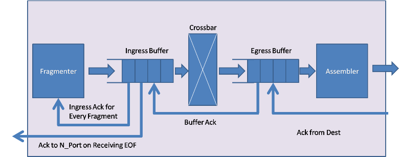
Fibre Channel Switch fragments the incoming frame to the fragment
size and forwards it to Ingress Buffer. Each fragment is acknowledged by
the Ingress Buffer before the next fragment is sent out. The Fibre
Channel Switch can support up to 16 or 96 F Ports to connect N_Port and
4 E Ports to connect to Switches. There is a unique fragmenter block
per port.
Ingress buffer has a dedicated queue for each connection and
forwards transactions from the respective queue to Egress Buffer based on
the flow control. Class1 messages are sent out as soon as the Egress Buffer is available. However class2 and class3 implements
buffer-to-buffer flow control.
Each port will has a dedicated counter
that monitors the number of transactions sent. This counter is used to
test for available buffer space in the Egress Buffer. For every
transaction sent, the counter is incremented by one. For class 2 and
Class 3, Ingress Buffer waits for an acknowledgment from the
egress buffer. On receiving the acknowledgment, the counter is
decremented by one for the corresponding port.
Crossbar switch has
16*16 or 96*96 dedicated channels to make sure that there are no
collisions. The Crossbar has a delay associated with it. The delay is
based on the fragment size and Switch_Speed_MHz. Egress
Buffer acknowledges every fragment sent from Ingress Buffer. If the
transaction arrives at a device connected to the current fabric
block, then the transactions are assembled; else transactions are sent
to a corresponding switch via E_Ports. Once all fragments are
received at the Egress port, the fragments are assembled into the
original transaction. Egress receives the Ack from the Ingress of the
next switch or the Destination N_Port. Once it receives Ack
from next switch or destination N_Port, it transmits the next
transaction.
Flow
Diagram
Flow Control
Flow control depends on class of service.
Flow control is unique for each Class. Class 1 and Class 2
keep track of the number of buffer locations available at the
destination before transmitting the next transaction. Class 3
does not require any end-to-end Ack. Class 1 transfers
from Ingress to Egress within a Switch. Class 2 and 3 require
buffer-to-buffer flow control.
Data
Structure Fields
FC_Switch requires few mandatory fields included in the A_Source,
A_Destination, A_Command ("Read"/"Write"), A_Message (initialized with
Class1, Class2 or Class3), A_Bytes, A_Bytes_Remaining, and A_Bytes_Sent are
the required fields.
Example:
input.A_Source
= "Device_1"
input.A_Destination
= "Device_9"
input.A_Command
= "Write" /*"Write"*/
input.A_Message
= "Class1" /*"Class2" or "Class3" */
input.A_Response
= "false"
input.A_Bytes
= 15000 /* Bytes */
input.A_Bytes_Sent
= 2112
input.A_Bytes_Remaining = 12888
A_Source field represents the name of the Source device, A_Destination
field represents the Destination device name, and A_Command is to identify
whether the transaction is a Read/Write transfer. A_Message helps one
to set type of service. Note that the Field values can be either
"Class1", "Class2" or "Class3". Purpose of A_Response field is to
identify if a transaction is a response from Destination device or a
transaction from Source device.
A_Bytes field has total size of the
packet and A_Bytes_Sent field gets updated with Fragment Size plus Overhead
Bytes in Fibre Channel Switch.
A_Bytes_Remaining has the details about
remaining fragment size waiting for transmission.
Parameters
|
Name
|
Type
|
Description
|
|
Switch_Name
|
String
Ex: “FC_Fabric_1”
|
Name
of Fibre Channel Switch
|
|
Ingress_Buffer_Size
|
Integer
|
Size
of Ingress Buffer at each port
|
|
Egress_Buffer_Size
|
Integer
|
Size
of Egress Buffer at each port
|
|
Architecture_Name
|
String
|
Name
of Arch_Setup
|
|
Fragment_Size
|
Integer
|
Size
of Frame Fragment
|
|
Overhead_Bytes
|
Integer
|
Overhead
Bytes
|
|
Enable_Debug
|
Boolean
|
Enable
or Disable Debug Message
|
|
Switch_ID
|
Integer
|
Unique
Identifier for Fabric Switch
|
FC_Link
FC_Link block models the physical communication medium. User can define
the length in meters and also the delay associated with the type of
communication medium.
Parameters
|
Name
|
Type
|
Description
|
|
Length_In_Mtrs
|
Integer
Ex: 2
|
Length of Communication Medium in
Meters.
|
|
Dly_Per_Mtr
|
Double
Ex: 5.0e-9
|
Fibre Channel Delay per meter.
|
|
FC_Link_Dly
|
Double
Ex: Length_In_Mtrs * Dly_Per_Mtr
|
Computed Fibre Channel Link Delay.
Do not Change this parameter.
|
FC_Config
FC_Config block is part of Fibre Channel library. Block handles routing
information between one end system to another. By default Source and
Destination Device names are defined as Device_1, Device_2…Device_16.
Parameters
|
Name
|
Type
|
Description
|
|
Device_Configs
|
Data Structure.
Type: String
|
The
content can be placed directly in the window, in a file (TXT or CSV) or
a reference to another database block (extern).
Each row defines which Destination
device is connected to which Fabric Switch.
|
|
Switch_Configs
|
Data Structure.
Type: String
|
Number
of rows are based on number of Fabric Switches used in the System. Switch_Idx defines the Switch ID and the field
Connected_Switches is a two dimensional array. As Switch supports upto
4 Switches connected to a Switch block, max length of the array would
be 4. If there are multiple switches connected to a single E-Port
by cascading, then the
connected switches are defined here. An example is shown below.
|
Switch_IDx
Connected_Switches
E_Port_Address
;
2
{{1,3}}
{{4,1}}
;
1
{{2},{3}}
{{1,1},{4,1}} ;
3
{{1}}
{{1,1}}
;
|
|
Tutorial
Multiple demonstration system models are provided with documentation to
guide a user to adopt VisualSim Fibre Channel Library for conducting
early system exploration of Fibre Channel based system. Purpose of the
following tutorial is to introduce VisualSim Fibre Channel libraries
and understanding basic rules that need to be followed during model
construction.
Block diagram of a simple Fibre Channel based system with single Fibre
Channel Switch and two end systems is shown below.
Figure 1.0: System Block
Diagram
Here we have two end systems, Node-1 and Node-2 connected over a Fibre
Channel network. Node-1 acts as the source (Ex: Host) and Node-2 acts
as a destination device (Ex: Storage). Requests can be either Read
request or Write request, can be Class1, Class2 or Class3 type of
service. Fiber can be either single-mode or multi-mode
variant and based on the type of variant user can define the length and
delay associated with the fiber.
After the model construction is over, user can vary the type of service,
packet size, Request type, Link distance, Switch Speed, and so on and analyze the
system behavior under different configurations.
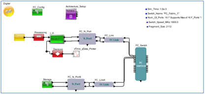
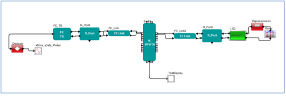
VisualSim model of the proposed system model is shown in figure below.
Figure 2.0: VisualSim
Model
Basic
Rules
- All the Source and Destination FC_N_Port IDs should be in
accordance with the connected port number of FC_Switch. If Device_1 is
connected to FC_Switch port number 1, then FC_N_Port ID should be
configured as 1.
- Each Source Device should have the following Data Structure
fields. Processor_DS Data Structure is recommended.
input.A_Source
= "Device_1"
input.A_Destination
= "Device_9"
input.A_Command
= "Write" /*"Write"*/
input.A_Message
= "Class1" /*"Class2" or "Class3" */
input.A_Response
= "false"
input.A_Bytes
= 15000 /* Bytes */
3. FC_Config block should be present in all Fibre Channel related
models. Source and Destination Names should be updated in
End_Point_Table if the names are other than Device_1,
Device_2….Device_16.4. Architecture_Setup
block should be present in the Construction Steps.
To construct a Fibre Channel Network model, there are five steps.
1. Instantiate Config and
Update the Device_Configs and Switch_Configs tables.
2. Instantiate and configure FC_TG,
FC_N_Port, FC_Link and FC_Switch blocks.
3. Connect FC_TG block to the N_Port.
Configure FC_TG block, N_Port, Switch and Config blocks.
4. Run simulations and Analyze Reports.
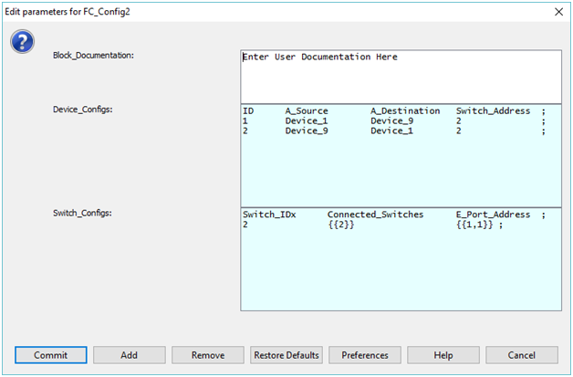
Step1
1. Instantiate FC_Config block from
Hardware_Modeling > Emerging Bus Standards > Fibre Channel > FC_Config.
Update Device_Configs and Switch Configs as shown below.
Step2
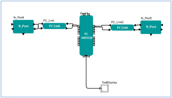
1. In this step, we shall add
FC_N_Port, Switch, and Link blocks.
2. Drag two instances of FC_N_Port from
the library pane
Interfaces and Buses >
Fibre_Channel > FC_N_Port.
3. Drag two instances of FC_Link from the
library Interfaces and
Buses > Fibre_Channel > FC_Link.
4. Drag one instance of FC_Switch from
the the library pane
Interfaces and Buses >
Fibre_Channel > FC_Switch.
5. Connect the Blocks as shown below.
6. Double click the N_Port (N-Port4 in the
above figure) block and set ID as 1, double click on N_Port2 (N_Port3
in the above figure) block and set ID as.
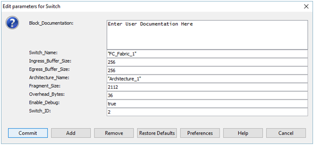
7. Double click the FC_Switch block and
configure the block as below.
Step3
In this step, we connect the traffic generator and modeling
destination devices using VisualSim basic building blocks.
1. Instantiate FC_TG from the library
pane
Interfaces and Buses > Fibre_Channel > FC_TG.
2. Double click the FC_TG block.
- Configure the block
parameter Device_Name as “Device_1”.
-
Configure the parameter Frame Details as below table.
ID
A_Source
A_Destination A_Message
A_Bytes
Trig_Start_Time
Stop_Time A_Command A_Response
Mbps
;
1
Device_Name
"Device_9"
"Class1"
6600
0.0
1.0e-3
"Write"
false
1000.0 ;
2
Device_Name
"Device_9"
"Class1"
6600
1.0e-3
10.0e-3
"Write"
false
1000.0 ;
3
Device_Name
"Device_9"
"Class2"
6600
10.0e-3
15.0e-3
"Write"
false
1000.0 ;
4
Device_Name
"Device_9"
"Class3"
6600
15.0e-3
20.0e-3
"Write"
false
1000.0 ;
3. Instantiate Delay block from the
library pane
Delay and Utilities > Delay. Double click the block and
enter Delay_Value as 5.0e-8.
4. Instantiate Expression_List or
Processing block from the library pane. Define the expression as below
under Expression.
input.A_Command =
(input.A_Command == "Read")?"Write":"Read"
5. Connect the Delay block to output port of
I_O2 block and input port of Expression_List or Processing block to
Delay block and output port of Processing block to input port of I_O2
block.
6. Connect to_bus and from_bus ports of
I_O2 block to Device_In and Device_Out ports of FC_N_Port2 block.
7. After all the connections are
successful, VisualSim model is as below.
Step4
In this step we configure the model for capturing statistics and
end-to-end latency.
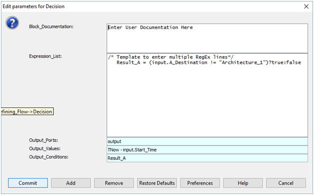
1. Connect data_out port of FC_TG block
to a Decision block and configure the Decision block as below.
2. Instantiate xTime_yData Plotter from
the library pane
Results > Plotter > TimeData plotter.
3. Connect output port of Decision block
to input port of plotter.
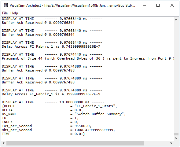
Reports
Throughput Statistics
End-to-End
Latency
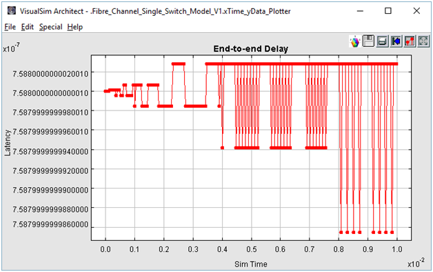
Analysis
1. Change type of service by
changing Class1, Class2, and Class3.
2. Increase/Decrease Packet size by
changing A_Bytes value.
3. Vary FC_Link Dly_Per_Mtr and
Length_In_Mtrs.
4. Modify FC_Switch Switch_Speed_MHz,
Buffer Size, and Overhead_Bytes.

