TTEthernet is a scalable, open real-time Ethernet platform used for safety-related applications primarily in transportation industries and industrial automation. TTEthernet sets new standards for flexibility, modularity, and scalability in Ethernet-based systems. It is compatible with IEEE 802.3 Ethernet and integrates transparently with Ethernet network components.
VisualSim TTEthernet library is completely compliant with TTEthernet specifications from TTTech. TTEthernet library package includes TTEthernet node, Traffic Generators, TTEthernet Bridge, and Statistic generators. In addition to the standard library modules, VisualSim also has preconfigured TTEthernet Configuration tables which include routing table, Bandwidth allocator, stream table, VLAN table, and Traffic generator table.
VisualSim
TTEthernet library can be used to design a completely new TTEthernet
based system or integrate with a system in which multiple different
protocols exist.
Below is a brief explanation on each TTEthernet library block.
A demonstration system is provided with explanation on the use of this library. The block diagram is provided below:

Figure 1.0 Block Diagram of Simple TTEthernet Network
Node 1 and Node 2 are the synchronization masters, Node 5 acts as a Synchronization client, and Bridge acts as a compression master in figure 1.0. Each Source node’s (Node1 & Node2) or Synchronization masters can generate messages of Time-Triggered (TT), Rate-Constrained (RC) or Best-Effort (Ethernet). Node 1 and Node 2 transmit messages to a single client Node5 which is connected by a Bridge in between.
Open this model in VisualSim from the following location:
File->Open File
$VS/doc/Training_Material/Tutorial/WebHelp/Tutorial/Networking/TTE_Simple_Example.xml
. A bunch of different test cases using TTE is provided in the same
directory.
Each
node consists of one traffic generator which can generate messages of
TT, RC and Ethernet; and a node block. The bridge uses the TTE_Bridge
block. As Node_5 is a client, we have connected TTE_Stats to it to
generate network statistics and stream latency. The TTE_Config_Table
and TTE_Setup blocks are added to this block diagram editor to define
network attributes. Users have to define the following top level model parameters:
The Digital simulation is added with a stop time. When you run the simulation, there are four outputs. There are two plots - one displaying the latency for all the streams and the other is a Histogram of the latency. There are two text files that are written at the end of the simulation - one contains information and warning messages, and the other contains the latency statistics for each stream.
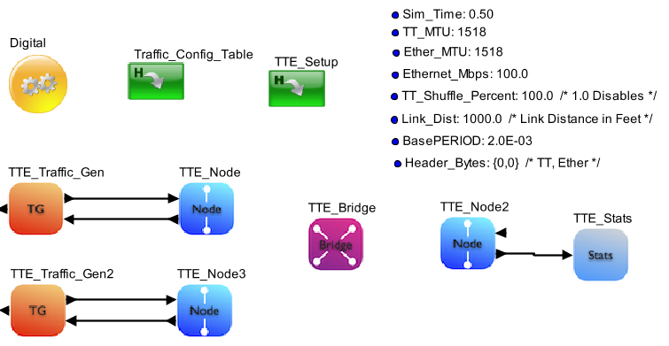
Figure 2.0 VisualSim Model
Basic Rules
To construct an TTEthernet model, there are five steps.
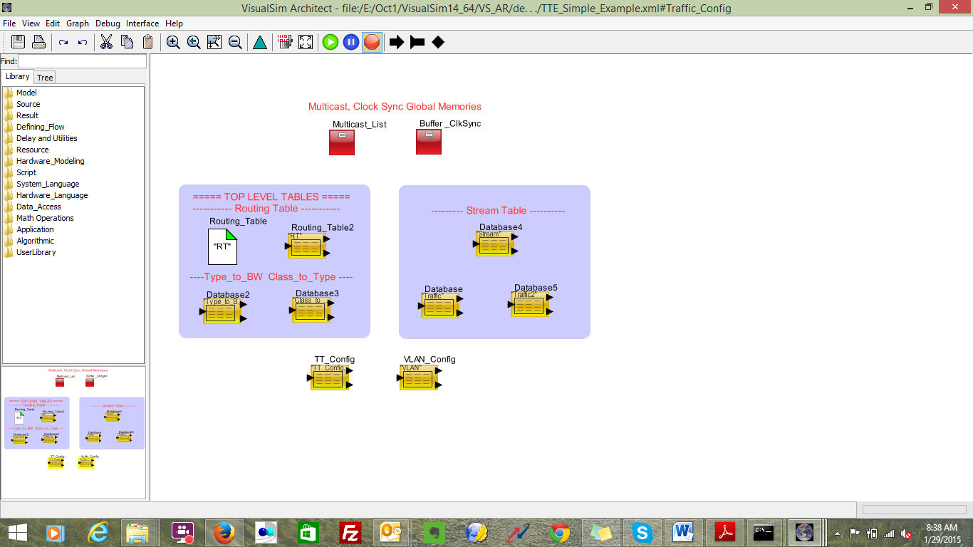
Figure 3: TTE_Config_Tables
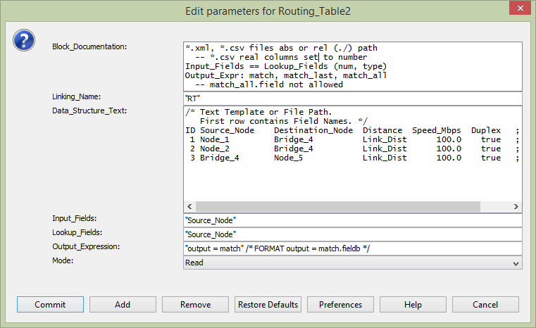
Figure 4: Routing Table Configuration
ID Type Mbps ;
0 0 0.0 ;
1 1 0.0 ;
2 2 0.0 ;
3 3 1.0 ;
4 4 1.0 ;
5 5 33.0 ;
6 6 25.0 ;
7 7 40.0 ;
ID: Increasing sequence number starting from 1.
Type: Type of Class. The values are 0 to 7
Mbps: Bandwidth allocation. The sum of all the rows of this column must not exceed the total bandwidth of the links.
Full Format is
ID Type Node_1 Node_2 Node_3 Bridge_4 Bridge_5 Node_5 ;
0
0 0.0 0.0
0.0 0.0
0.0 0.0 ;
/*
Background
*/
1
1 0.0 0.0
0.0 0.0
0.0 0.0 ;
/* Best
Effort
*/
2
2 0.0 0.0
0.0 0.0
0.0 0.0 ;
/* Excellent
Effort
*/
3
3 1.0 1.0
1.0 1.0
1.0 1.0 ;
/* Video 50ms
latency */
4
4 1.0 1.0
1.0 1.0
1.0 1.0 ;
/* Critical
Apps
*/
5 5
25.0 25.0 25.0
33.0 33.0
33.0 ; /* Video 2ms
latency */
6
6 25.0 25.0
25.0 25.0
25.0 25.0 ; /*
Internet
Control
*/
7 7
40.0 40.0 40.0
40.0 40.0
40.0 ; /* Network Control,
highest */
ID: Increasing sequence number starting from 1.
Type: Type of Class. The values are 0 to 7
Node_1,
Bridge_1...: Bandwidth allocation. The sum of all the rows of each
column must not exceed the total bandwidth of the link.
Please make sure that you have included all the available nodes in the model
1.6 Class_to_Type- For each Bridge and Node in the model, the mapping of Type to Class and B.
Sample table is as shown below
ID Class Type ;
0 A 4 ;
1 B 3 ;
ID: Increasing sequence number starting from 1
Class: A or B
Type: Type of Class. The values are 0 to 7. Common to all Nodes and Bridges in the model.
Full format is
ID Class Node_1 Node_2 Node_3 Bridge_4 Bridge_5 Node_5 ;
0
A
4
4
4
4
4
4 ; /*
Background
*/
1
B
3
3
3
3
3
3 ; /* Best
Effort
*/
ID: Increasing sequence number starting from 1
Class: A or B
Type: Type of Class. The values are 0 to 7. Common to all Nodes and Bridges in the model.
1.7 TT_Config_Table:
TT_Config table provides the timing precision for Time-Triggered
messages. StartTime is computed based on the task size and the Network
Speed. User should enter details for the complete flow, for example if
Source node is Node_1 and the destination is Node_5 then all the Nodes
and bridges involved in communication flow should be defined in the
table.
Sample TT_Config_Table is shown below
Node
TTName StartTime
BasePeriod ProcTime ;
"Node_1"
"TT1" 1.25E-03
BasePERIOD ProcTIME ;
"Node_2"
"TT1"
2.0E-03
BasePERIOD ProcTIME ;
"Node_3"
"TT3"
3.0E-03
BasePERIOD ProcTIME ;
"Bridge_4"
"TT1"
2.5E-03
BasePERIOD ProcTIME ;
"Bridge_4"
"TT2"
3.0E-03
BasePERIOD ProcTIME ;
"Bridge_4"
"TT3"
3.5E-03
BasePERIOD ProcTIME ;
"Bridge_5"
"TT1" 3.0E-03
BasePERIOD ProcTIME ;
"Bridge_5"
"TT2" 3.5E-03
BasePERIOD ProcTIME ;
"Bridge_5"
"TT3" 4.0E-03
BasePERIOD ProcTIME ;
"Node_5"
"TT1" 3.5E-03
BasePERIOD ProcTIME ;
1.8 VLAN:
No change is required. In this table based on the VLAN ID BAG is
allocated. For the Rate Constrained traffic stream, this table decides
the allocated bandwidth for a given VLAN. User can have as many VLANs
and associated with BAG and LMax time. Sample VLAN table is shown below;
ID VLAN BAG LMax ;
1
1 1.0e-6
256 ;
2 2 1.5e-6 512 ;
3 3 2.0e-6 1024 ;
4 4 2.0e-6 1024 ;
5 5 2.0e-6 1024 ;
Step2
In this step we will add the blocks required for pre-processing the tables. This block must be added to all TTE models or models that use the TTE blocks. This block does require the existence of the Traffic tables, Routing Table, Link Setup table, Type_to_BW table, Class_to_Type, TT_Config_Table table, and Multicast Memory_Init block.
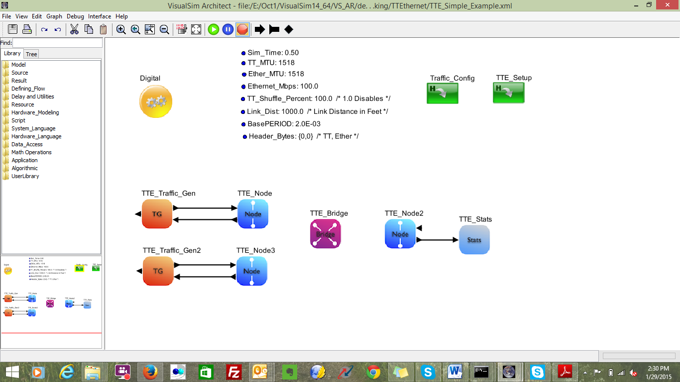
Figure 5: Assembly of Source Node
At the receiver side or client side only Node block is sufficient. To collect network activities and statistics, one can connect TTE_Stats to the client node block. The assembly of the two blocks is as shown below.
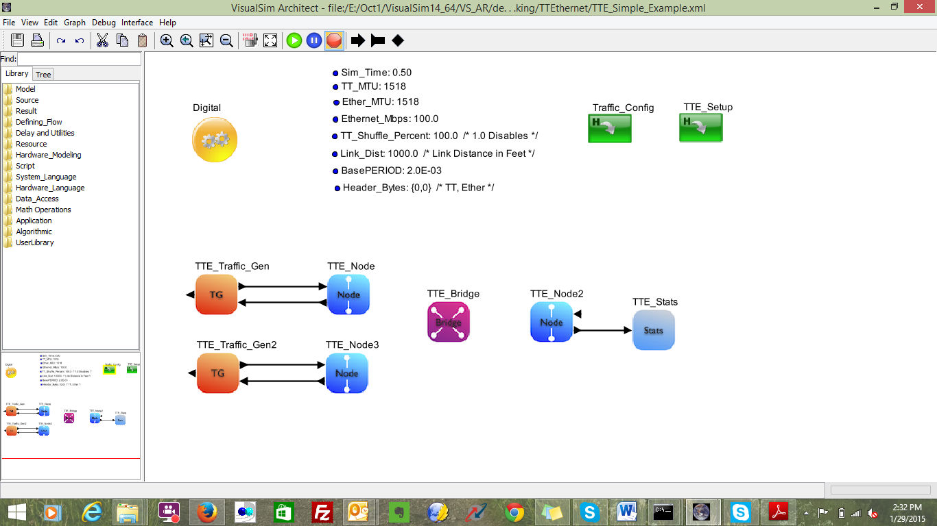
Figure 6: Assembly of Client Node/ Destination only node
The Bridge connects the Nodes to the network and also connects to other Bridges. The bridge block handles the Routing and broadcast of clock synchronization. A model can have a single bridge with all the Nodes connected to it.
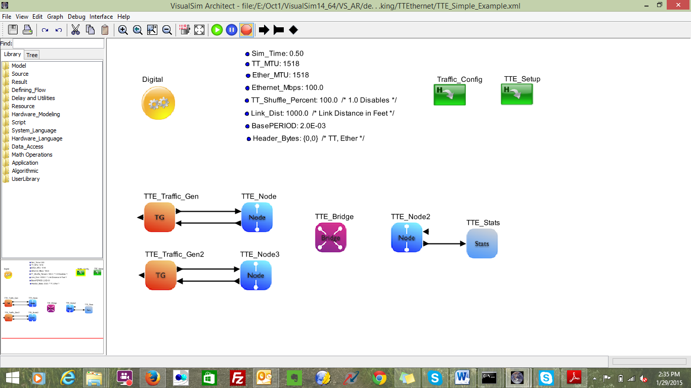
Figure 7 Single Bridge Network
If a model has multiple bridges, instantiate as many TTE_Bridge blocks and update the Link_Setup. The topology of the network is determined by the Link_Setup table. The Block Diagram shows the number of Bridge and Node instances.
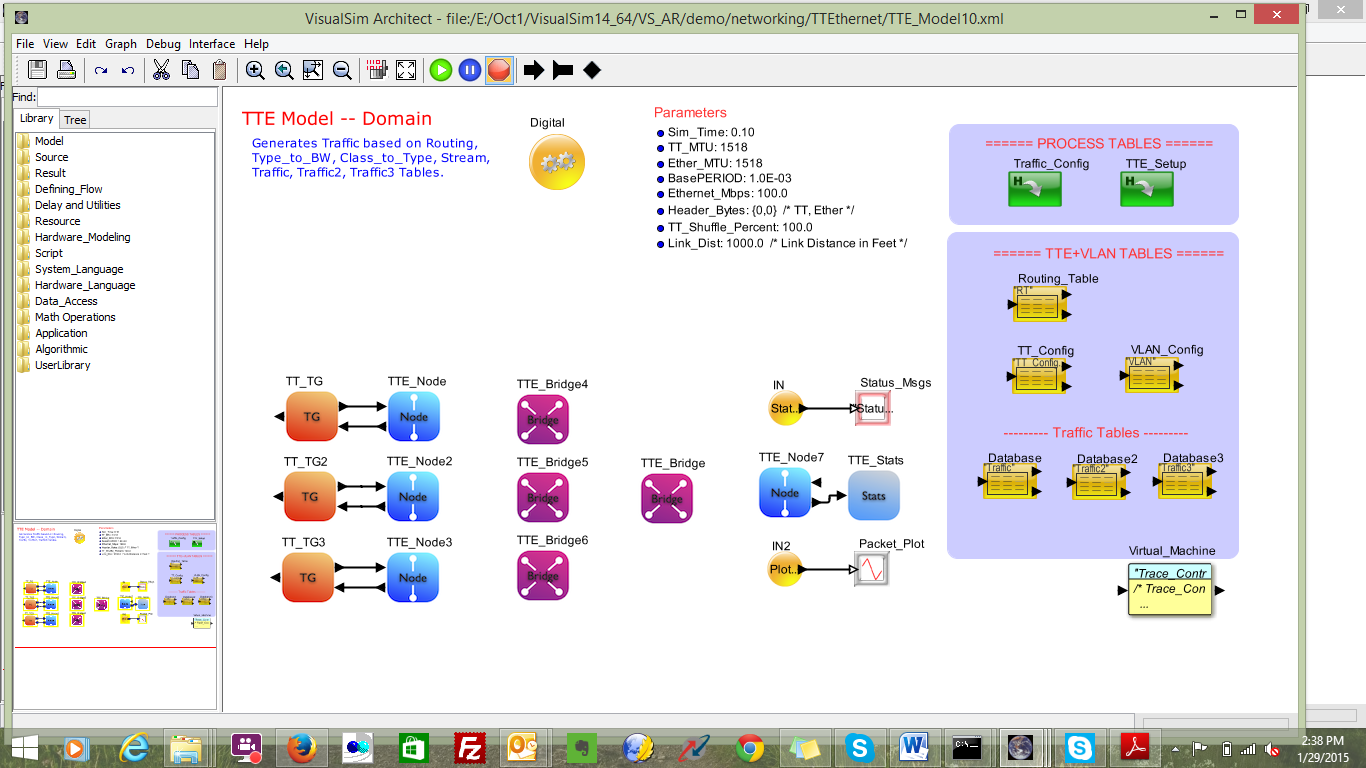
Figure8 Multiple Bridge Network
Time-Triggered |
Rate Constraint |
N1_to_N5_TT1_1 Latency Minimum: 2.5061367090 ms Mean: 2.5061367090 ms Std Dev: 29.1 ps Maximum: 2.5061367090 ms Throughput Mbps: 0.0328661952051 |
N2_to_N5_RC2_3 Latency Minimum: 24.5134240 us Mean: 494.2624945 us Std Dev: 571.1953459 us Maximum: 2.0779767120 ms Throughput Mbps: 0.5011401721222 |
Ethernet |
|
N1_to_N5_Ether_4 Latency Minimum: 14.2734240 us Mean: 519.6828018 us Std Dev: 617.3499543 us Maximum: 2.8099000580 ms Throughput Mbps: 0.3010222764019 |
|
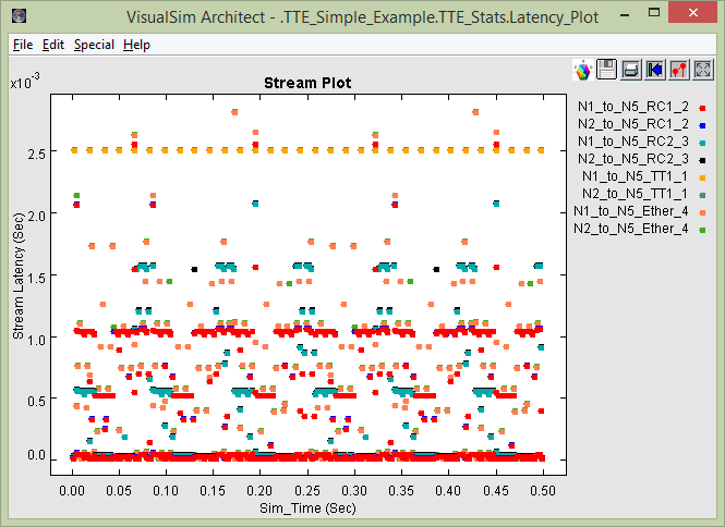
Figure 9: Stream Latency Plot
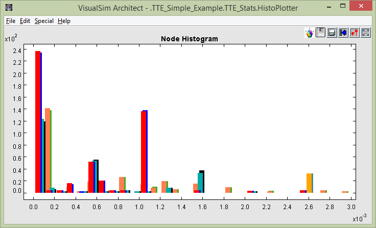
Figure 10 Histogram Latency plot
a. Connect an Interfaces and Buses > TimeTriggeredEthernet > TTE_Stats
block to the output of each of the Nodes. This captures all the
statistics including the activity traces, latency, and histogram plots.
You can see a unique latency graph at each Listener of Destination
Node. We only need this block for Nodes that receive data.
b. Enter the name of the Node that this block is connected.
Now the model is constructed. The next step is to run the simulation. Each simulation run can have different setup values - such as Network Topology (Link_Setup file), traffic streams from each node (Traffic table), number of TT/RC/Ethernet streams (stream table), and allocation of bandwidth to each Type at each Bridge (Type_to_BW).
For
each run, the statistics are provided in a combination of files and
graphical plots. View Step 6 to see the list of plots and reports.
Step1:
Extending System with additional Nodes and configure TTE_Config_Table.
Step2:
TTE_Setup
1.Update Traffic_Tables parameter with all additional Traffic_Table names.
Step3:
Run Simulation.
2. TTEthernet Model with 8 nodes and 3 Destination Nodes
In this tutorial we shall extend the model developed in advanced tutorial part 1.
Step1:
Open
the model developed in Part-1 and instantiate additional destination
nodes and TTE_Stats blocks. Provide unique names for TTE destination
nodes.
Step2:
Open
TTE_Config_Table block and update Routing Table(RT), Type_to_BW,
Class_to_Type, TT_Config, and Traffic Table. With Regards to Traffic
table, the user can decide which Destination node should be selected.
Step3:
Run the Simulation.
Note:
Final version of the model is available in
VS_AR\doc\Training_Material\Tutorial\WebHelp\Tutorial\Networking\TTE_8_Nodes_3dest_Nodes.xml.
3. TTEthernet Model with 8 Nodes, 2 Bridges and 3 Destination Nodes
In this tutorial, we shall extend the model developed in advanced tutorial Part2.
Step1:
Open the model developed in Part-1 and instantiate additional 1 TTE_Bridge block. Provide a unique name.
Step2:
Open TTE_Config_Table block and update Routing Table(RT), Type_to_BW, Class_to_Type, TT_Config, and Traffic Table. In the RT table one can select the flow. A sample RT table is shown below.
ID Source_Node
Destination_Node Distance Speed_Mbps
Duplex ;
1
Node_1
Bridge_4
Link_Dist 100.0
true ;
2
Node_2
Bridge_5
Link_Dist 100.0
true ;
3
Node_3
Bridge_4
Link_Dist 100.0
true ;
4
Node_4
Bridge_5
Link_Dist 100.0
true ;
5
Node_5
Bridge_4
Link_Dist 100.0
true ;
6
Node_6
Bridge_5
Link_Dist 100.0
true ;
7
Node_7
Bridge_4
Link_Dist 100.0
true ;
8
Node_8
Bridge_4
Link_Dist 100.0
true ;
9
Bridge_4
Node_10
Link_Dist 100.0
true ;
10
Bridge_5 Node_10
Link_Dist
100.0 true ;
11
Bridge_5 Node_11
Link_Dist
100.0 true ;
12
Bridge_4
Node_12
Link_Dist 100.0
true ;
Step3:
Run the Simulation.
'
Note:
Final version of the model is available in
VS_AR\doc\Training_Material\Tutorial\WebHelp\Tutorial\Networking\TTE_8_Nodes_3dest_Nodes_2Bridge.xml
VS_AR/demo/networking/TTEthernet/TTE_Simple_Example.xml
VS_AR\doc\Training_Material\Tutorial\WebHelp\Tutorial\Networking\TTE_8_Nodes_3dest_Nodes.xml
VS_AR\doc\Training_Material\Tutorial\WebHelp\Tutorial\Networking\TTE_8_Nodes_3dest_Nodes_2Bridge.xml