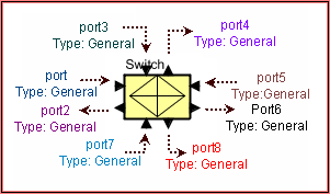
Hardware Devices / Switch
Block Name: Switch
Code File Location: VisualSim/actor/lib/bus/Serial_Switch
o The Serial Switch is a serial mesh crossbar switch with a point-to-point connection between each source (A_Source) and destination (A_Destination). The standard block has 16 Input/Output Device connections. Multiple Channels can be defined to each Source-Destination combination. This block supports Power estimation. This block supports multiple PHYs to be connected to each Channel. In this case, multiple bits can be transfered in parallel for each Channel. To additional devices beyond 15, the user must add additional ports. You cannot concatenate multiple switches to create a bigger switch.

This switch transfers requests from each Source (A_Source) to each Destination (A_Destination) in a First Come-First Serve order. Each Source-Destination combination has a separate queue. There are multiple channels assigned for each Point-to-Point connection. The transaction is assigned to a channel based on the value in the Field Name containing the channel. Multiple channels can be dynamically created during a simulation just by the value in the Channel Field. The Number_of_PHY parameter specifies the number of parallel bits that can be transfered within each Channel. This has the effect of multiplying the Clock_Speed for the Channel. If multiple transactions arrive from the same Source with different Channel numbers and to the same destination, they can be transmitted immediately if the channel is available.
There is a 32-bit address delay for each Read Request and a multi-cycle delay based on the length of the transaction for a Write. Cycle_Time is 1.0e-6/Speed_Mhz. The user can add additional cycles for the Read and Write by entering this in the Overhead_Cycles field.
The Overhead cycle is for each transfer and a extra cycle is added for each additional PHY greater than 1.
The following delay calculations are done within the Serial Switch block:
For Read or any non-Write Transfer: (Overhead + 32)*(1.0e-6/Speed_Mhz)*(Number_of_PHY)
For Write: (Overhead + (A_Bytes_Sent *8))*(1.0e-6/Speed_Mhz)*(Number_of_PHY)
For Write (Serial Rapid IO): (Overhead + (RIO_Data_Size *8))*(1.0e-6/Speed_Mhz)*(Number_of_PHY)
If zero delay is required across the switch, the Speed_Mhz must be set to 0.0.
The A_Command field contains the Command name. This can be Write or any other Type.
When the Channel is transfering data across any channel, the Switch is set to Active Power State. When the Channel is idle, it is set to Standby Power State. The user can create logic external to the block to change the power state and the power level. There is no power computation for each channel. Currently, this is a very rudimentary power analysis. If there are multiple PHYs, it is the user responsibility to modify the Power levels to accomodate for the multiple parallel data transfers. When switching States, the Channel waits for the Power Cycles before starting the transmission.
This block bypasses the "Hello Messages" from Architecture components and connects across multiple buses. No routing Table definitions are required for the devices connected to Buses that are directly connected to ports of this bus . if a device such as a Processor or DRAM is connected directly to the Switch Port, then this entry is required in the Routing Table.
The following fields are required for the correct operation of this block: A_Command, A_Bytes_Sent, A_Source and A_Destination.
Refer the Non-blocking Switch demo model for more details.
Parameter |
Explanation |
Type |
Example |
Architecture_Name |
This is the name of the ArchitectueSetup block that this switch is associated for the purpose of the Routing Table. |
String |
"Architecture_1" |
Switch_Name |
This is an unique name for this block. No other Architecture, Scheduler or Resource must have this name. |
String |
"Switch" |
Speed_Mhz |
This is speed of the Switch and is in Mhz. Internally the speed is converted to Mbps for determining the delay across the switch. |
Double or RegEx |
500.0 |
Channel_Field_Name |
This is the name of the field of the incoming Data Structure Field that contains the channel number. The channel numbers start from 0. |
Integer |
"INDEX" |
Overhead_Cycles |
This is the number of additional cycles required for Read and Write operation. The Number of PHY - 1 is added to this number to account for the Serial to Parallel conversion at destination. |
Integer |
0 |
Sim_Time |
This is duration of the simulation and is used for the Digital Simulation inside. |
Double |
1.0 |
Number_PHY_Lanes |
This is the number of PHYs connected to each Source and Destination. It is assumed that all devices connected to this switch have the same number of PHYs connected. |
Integer |
1 |
Power_Manager_Name |
This is the name of the associated PowerTable. If the listed PowerTable is not available, power is not updated by this block. |
String |
"Pwr_Mgr_1" |
Switch_Buffer |
Buffer at each port of the switch. This is in bytes. |
Integer |
256 |
Enable_Messages |
This block outputs trace data and statistics. Statistics will always be output. True will send the data and false will not send the data out. |
Boolean |
true |
Custom_Algorithm_File |
This is the name of the file containing the arbitration logic. The file will be the Virtual Machine script format |
String |
"Arb_File.txt" |
Port |
Explanation |
port to port24 |
Device_1 to Device_24 input/output data structure. |
Created with the Personal Edition of HelpNDoc: Free CHM Help documentation generator