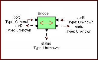
Hardware_Modeling / Bus_Switch_Ctrl/Bridge
Block Name: Bridge
Code File Location: VisualSim\actor\lib\bus\Bridge
o Connects two buses together.

The Bridge block is used to connect two Bus together. If the two connected buses are based on the Linear Port or Bus Port, there connected devices do not require a Routing Table entry.
Refer the Bridge demo model for more details.
Parameter |
Explanation |
Type |
Example |
Architecture_Name |
Name of the Architecture Setup block that is associated with this Bridge. |
String |
“Architecture_1” |
Bridge_Name |
It requires an unique name. This name must not be the name of any other architecture, scheduler or controller block. |
String |
“Bridge1” |
Bridge_Speed_in_Mhz |
Speed of the Bridge. The base unit is MegaHertz. |
Double |
500 |
Bridge_Width_in_Bytes |
This is the width of the bridge. If the bus width is 4 cycles and the transfer size is 8 bytes, there will be a two cycle delay across the bridge. |
Integer |
8 |
Overhead_Cycles |
This is the additional cycles that match the hardware processing delay. |
Integer |
4 |
Width_Bits |
This parameter must be added to this block, if the number of bits is not a multiple of 8 (bytes). In this case the Bridge_Width_in_Bytes must be set to 0. If both the Bytes and bits are set to 0 or bot set all all, the default width is 32 bits. |
integer |
4 |
Port |
Explanation |
port |
Input port from the left Bus. |
port3 |
Input port to right bus. |
status |
Receives messages about bridge operation and output utilization at the end of the simulation. |
port2 |
Output port to left bus. |
port4 |
Output port to right bus. |
Created with the Personal Edition of HelpNDoc: News and information about help authoring tools and software