![]()
Laboratory - Modeling using Serial Rapid IO
The objective of this model is to explore the usage of Serial Rapid IO with memory and other peripheral devices.
The model has configurable DDR3 memory, SRIO, IO, and a serial switch as hardware architecture elements.
The model has mainly two peripheral devices that are modeled as traffic sources and are Communication devices and an Instrument panel. Instrument panel reads the data that are available on memory and the Communication device writes the data to memory.
The results are focused on analyzing end-to-end latency of read and write operations, total power consumption, and SRIO throughput.
Block Diagram
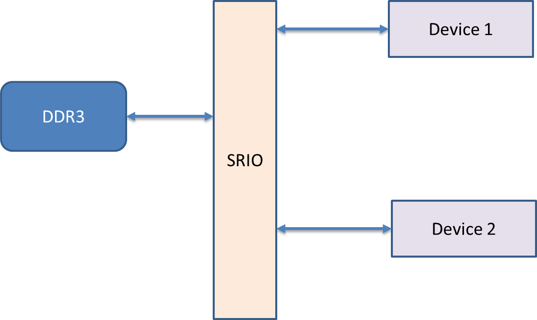
Figure 1.0: System Block Diagram
Model Objectives
1. Create a traffic source that resembles a communication device and Instrumentation panel.
Potential Blocks > Traffic, Processing
2. Instantiation of Memory devices, Serial_Switch, IO, and Model Hardware part of the system.
Potential Blocks > DRAM, Serial_Switch, I_O, SRIO_Node
3. Analyze average and peak power consumption by the complete system.
Potential Blocks > Power Manager, TimeDataPlotter
4. Compute End-to-End Latency and generate utilization statistics.
Building the Model
Step 1: Create a new block diagram
1. Open a new block diagram by selecting File > New > Block Diagram Editor.
2. Save this diagram in the desired directory by selecting menu File > Save As and filling out the "Save As"dialog box.
3. Instantiate a model parameter by dragging ModelSetup > Parameter= on to the block diagram.
1. Right- click on this parameter and select menu Customize Name.
2. Type “Sim_Time” as the name of the parameter and hit the “Commit” button.
3. Double-click on this parameter and specify a value of 500.0E-03 (feel free to change this value as you experiment with this model).
4. Instantiate a “Digital” simulator block from the library pane ModelSetup > Digital.
1. Double click on the “Digital” block and type in “Sim_Time” for the block parameter "stopTime".
Step 2: Create environment using Traffic Generators
1. Instantiate a “Traffic” block by dragging on to the block diagram editor. Traffic block is located in Traffic > Traffic.
1. Double click the Traffic block and enter value “Processor_DS” for Data_Structure_Name parameter.
2. Double click the Traffic block and change the block parameter “Time_Distribution” to Fixed(Value_1) and click the “Commit” button.
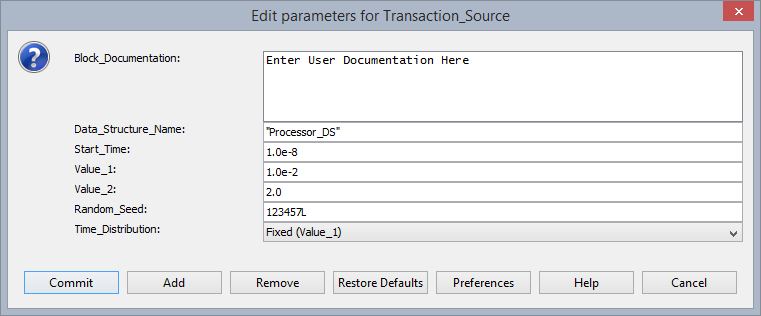
Figure 1.1- Configuring Transaction Source - Instrument
2. Instantiate a “Processing” block by dragging on to the Block diagram editor. Processing block is located in Full Library > Defining_Flow > Processing.
1. Double click on “Processing” block and enter the below RegEx expressions in the block parameter “Expression_List”.
input.A_Source = "Instrument"
input.A_Destination = "SDRAM"
input.A_Bytes = 4096
input.RIO_Sender_Mailbox = 1
input.RIO_Receiver_Mailbox = 4
input.A_Command = "Read"
Click the “Commit” button
Now you have created traffic generator that resembles Instrumentation Panel activity.
Similarly instantiate another Traffic and Processing block to model Communication device traffic. Refer figure 1.2 and figure 1.3.
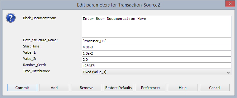
Figure 1.2- Configuring Transaction Source – Communication
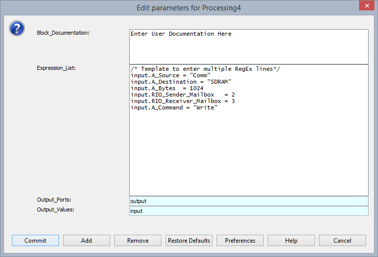
Figure 1.3- Configuring Processing block – Communication
Step 3: Instantiation of Hardware Architecture elements
1. Instantiate two DeviceInterface blocks from the library panel Hardware Setup > Device Interface. ConfigureDevice_Interface (I_0 block) blocks as shown in figure 1.4
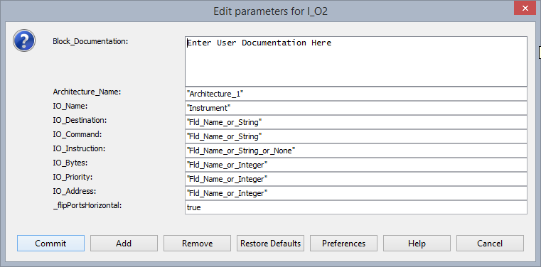
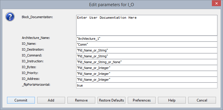
Figure 1.4
2. Instantiate three SRIO blocks from the library panel, Interfaces and Buses > Rapid_IO > RIO_Node. Configure RIO_Node as shown in figure 1.5.
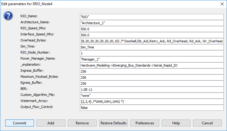
Figure 1.5 : Configuring SRIO Node
3. Instantiate DRAM library block from the library panel, Hardware Modeling > Core_Architecture > DRAM. Configure DRAM block as shown in figure 1.6.
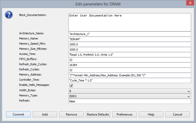
Figure 1.6 : Configuring DRAM
4. Instantiate Serial switch library block from the library panel, Hardware Devices > Serial_Switch. Configure the Serial_Switch library block as shown in figure 1.7.
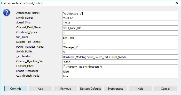
Figure 1.7: Configuring Serial Switch
Step 4: Power manager configuration
Instantiate Power Manager library block from the library panel, Power > Power Table. Configure Power Table library block as shown in figure 1.8.
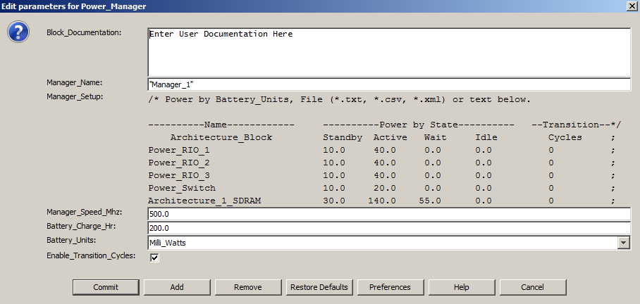
Figure 1.8: Configuring Power_Manager
Step 5: Compute Latency
1. Instantiate “Processing” block on to the block diagram editor.
a. Double click the “Processing” block and enter the expression “TNow – input.TIME” for block parameter “Output_Values”. Click the “Commit” button.
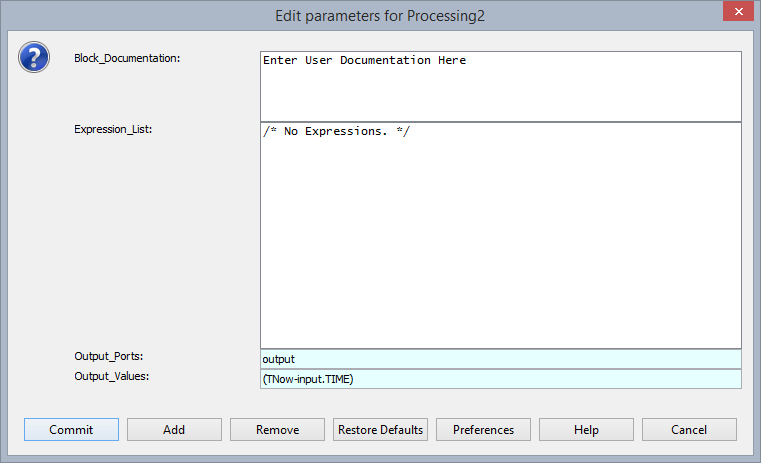
Figure 1.9
Save the design at this point.
Step 6: Making Connections
Using wires make the connections as shown in the figure 2.0.
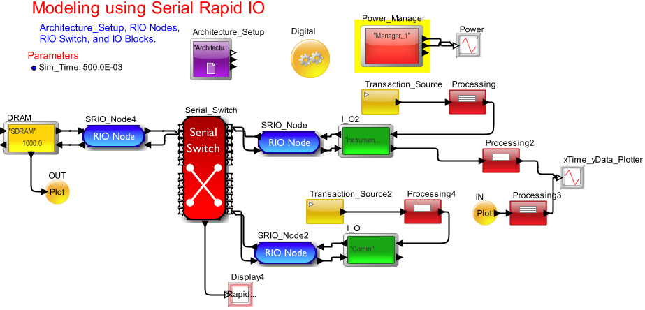
Figure 2.0: Complete System
Save the design at this point.
Step 7: Run simulation by clicking![]() button on the tool bar.
button on the tool bar.
Step 8: Vary library parameters of RIO, Serial Switch, DRAM, and Traffic rate to analyze latency and throughput for different system configurations.
Analysis
Scenario 1:
Double click the “Processing” and “Processing4” blocks and change input.A_Bytes = 4096 to input.A_Bytes = 1024. (Feel free to vary in a random range of 1024 to 4096). Double click the “Serial Switch” library block and vary the Speed_MHz parameter from 1000.0 to 800.0. Notice the Latency plot and statistics.
Scenario 2:
Double click the “Processing” and “Processing4” blocks and change input.RIO_Receiver_Mailbox = 2 in both Processing blocks. Notice the variations in the Latency plot.
Scenario 3:
Double click the Transaction_Source and vary “Value_1” to change the traffic rate. Change the value of Value_1 parameter from1.0e-2 to 1.3e-2.