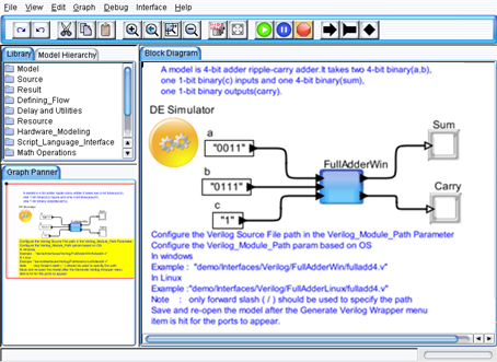
The example model shown in Figure 1 is located under demo/Verilog/FullAdder directory. This model uses a Verilog_Cosim Block, which takes three different inputs and two outputs.
Section Using the Interface explains the steps involved in creating this model.

Figure 1. FullAdder model
This chapter explains on how to use and configure the Verilog_Cosim to interface Verilog code in VisualSim. The Verilog_Cosim is located in Full Library > Hardware_Language > Verilog. The block can be placed on the canvas in the same way as any other block. Once the Verilog_Cosim has been placed on the canvas, the block needs to be configured.
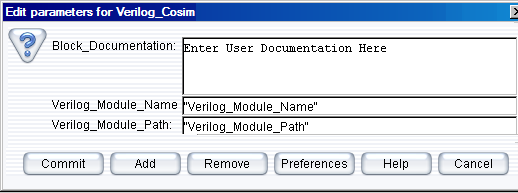
Right-click the Verilog_Cosim block and select Customize > Configure. This menu is used to specify the Verilog location and file name.
The parameters are as follows:

Figure 2. Configuring the Verilog_Cosim block
Note: The Verilog file name without the “.v” extension should match the Verilog Module Name.

Figure 3. Configure ports for Verilog_Cosim block
Click Add in Figure 3 to view the window in Figure 4. Double-click on the Name field and enter the field name. Select input or output type and the VisualSim data type (from the “Type” column).

Figure 4. Configure ports for Verilog_Cosim block
Now add the Remote Type with the Verilog type [width of the port]; Verilog PLI type.
The Remote type should be in double quotes. Here the format for specifying the Remote Type is:
Format: “Verilog Data types [width of the port]; Verilog PLI Format”
Example: “wire [0:3]; vpiBinStrVal”
Verilog Vpi input and output format |
Verilog Argument Types |
VisualSim port Types |
vpiBinStrVal |
wire, reg |
string |
vpiOctStrVal |
wire, reg |
string |
VpiDecStrVal |
wire, reg |
string |
VpiHexStrVal |
wire, reg |
string |
VpiIntVal |
Integer, wire, reg |
int |
VpiRealVal |
real |
double |
VpiStringVal |
reg |
string |
Table 1 Verilog Arguments and Equivalent Java Port Types
After the Verilog_Cosim block is configured, the interface template can be generated and compiled, which enables execution of the Verilog_Cosim block in VisualSim. Use the GUI menu Interface > Generate Wrapper shown in Figure 5 to generate Verilog Wrapper. Use the GUI menu Interface > Compile Wrapper in Figure 5 to compile the Verilog Code.
Figure 5. Menu Bar View to Select Generator
Note: Open the “vsout.txt” file under the Library Directory to check for any errors that occurred during the compilation process. This could help correct any mistakes in the interface Verilog code.
The Text_Display (Non-Buffered) block can be dragged on to the canvas from Result > Text. Similarly, the Const input block can be obtained from the Full Library > Math Operations > Math and Trig. Control-click to create the relations.
Connect all the blocks as shown in the Figure 1 and then add an Untimed Digital simulator (from ModelSetup) and change the number of iterations from 0 to 1 by double-clicking the Untimed Digital simulator.
Click the “Run” button in the IDE or press Ctrl+R to execute the model.
Codes for the respective Verilog demo model are saved as .v file located in the following directory:
demo\Interfaces\Verilog\(Name of the demo model)\(Name of the file).v
For ex: demo\Interfaces\Verilog\OrGateWin\orgate.v