Architecture Exploration

Parent Previous Next

Power Modeling and Analysis


VisualSim Model

Refer Fig 1 for the intended VisualSim Model.

Power Management VisualSim Model
Figure 1: VisualSim Model
VisualSim Model for the tutorial is available in the following location

$VS\doc\Training_Material\Tutorial\WebHelp\Tutorial\Architecture_Exploration\Processor_Modeling_Tutorial\Processor_Modeling_Part1_Power.xml

Building the VisualSim Model

In this model built for Scenario 3 of Architecture Exploration, drag and drop a PowerTable block ( Power Table block) from Power along with a TimeDataPlotter block to generate the power consumption details.
The block manages the power consumption, battery charging, dynamic system changes and impacts the system timing because of power state changes. The block uses the dynamic state change information of the devices during the simulation to output the instantaneous, average and discharge.


/* Power_Table.  First row contains Column Names, expressions valid for entries except Device Name.                                                
                                                                                                                                                   
--------Device Name-------         -------Power States-------------  -----Operating States------       ---State Transitions--  --Speed--  --Exist-- */
 Architecture_Block           Standby  Active  Wait     Idle         Existing    OffState  OnState      t_OnOff    Mhz       Volts   ;
Architecture_1_Processor_1  75.0     200.0   100.0  100.0     Standby   Standby   Active         1.0e-8    
1000.0     1.0    ;
Architecture_1_Processor_2  25.0     100.0    0.0      0.0        Standby   Standby   Active         1.0e-8     1000.0     1.0    ;
Architecture_1_L2_Cache      50.0     150.0    0.0      0.0        Standby   Standby   Active         1.0e-8     1000.0     1.0   ; 
Architecture_1_DRAM            10.0     100.0    0.0      0.0        Standby   Standby   Active         1.0e-8     1000.0     1.0   ;
Architecture_1_Bus_1            50.0     150.0    0.0      0.0        Standby   Standby   Active          1.0e-8     1000.0     1.0   ;


PowerTable Parameters
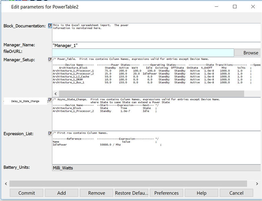
Figure 2: PowerTable Parameters

There are three additinal options available to the user- Delay_to_State_Change, Expression and use of block parameters and variables. All are captured in Figure 2. 

The Delay-to_State_Change is used to move the selected device from the current state to another state after a delay (Time).  See how the values are entered for Processor_2. 
The list of entities after the State_Transtion time in Manager_Setup are user-settable. Any number of parameters can be defined. The most common ones are speed, volt and LDO_Effciency.
The Expression_List window can use Regex, parameter, Manager parameters and variables to create the expression for a block variable.  This block variable can be used for the State power value columns.  If using the column parameter, the values in the same row as the usage of the variable are used.  The column names are the parameter names and can b used in the Expression. Notce the usage in Figure 2.


The instantaneous average power plotter displays a graph which is similar to the image given below.

AEA Inst Power Plotter
Figure 3: Instantenous Average Plotter