PIPE
PIPE is a basic example model to show how to use SystemC and user can use it as a template to create more complex models.
This model is taken from the SystemC Testing the Interface Class Library examples:
It consists of three processes that form individual stages of a pipeline.
Figure 1. Pipeline Design
The first stage of the pipeline accepts two inputs and computes their sum and difference. The second stage accepts the results of the first stage and computes their product and quotient. Finally, stage3 accepts these outputs from the second stage and computes the first input rose to the power of the second.
In the above diagram, only the stages of the pipeline has been showcased. Apart from this we require one more block or module that generates the random numbers that act as the inputs to the first stage of the pipeline.
So in our PIPE model, we have four SystemC modules namely SC_MODULE (numgen), SC_MODULE (stage1), SC_MODULE (stage2), and SC_MODULE (stage3) respectively. The model also contains the Digital Simulator (Model-Simulators) and the SC_Sim (Hardware Language > SystemC).
Let us focus on how to write the SystemC code and configure the SC_Module interface block to create the PIPE model as depicted above.
This chapter explains as to how to use and configure the SC_Module interface block to build your SystemC model in VisualSim. The SC_Module block is located in Full Library > Hardware_Language > SystemC. The block can be placed on the canvas in the same way as any other blocks as shown in the Figure 2. After the SC_Module has been placed on the canvas, the block needs to be configured.

Figure 2. SC_Module block placed on the editor space
Right click on the SC_Module block and choose Customize > Configure to configure the block parameters as shown below:

Figure 3. Configuring the SC_Module block
The parameters are as follows:
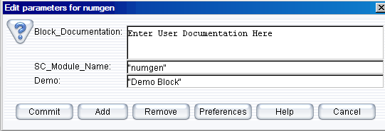
The parameter SC_Module_Name is the name of the SC_MODULE in SystemC and it is also the directory name for the block that is created under the SystemC directory. Just the directory structure within this level is sufficient. To add an additional parameter, for example, Demo. Click Add in figure 3, Add a new parameter to ..SC_Module window is displayed. Enter the parameter details as shown in the following figure:

Figure 4. Add new parameter
Right click on the SC_Module block and select Open Block to write the SystemC code.
The editor window has the basic template code as shown in the Figure 5:

Figure 5. Editor window to write the SystemC code
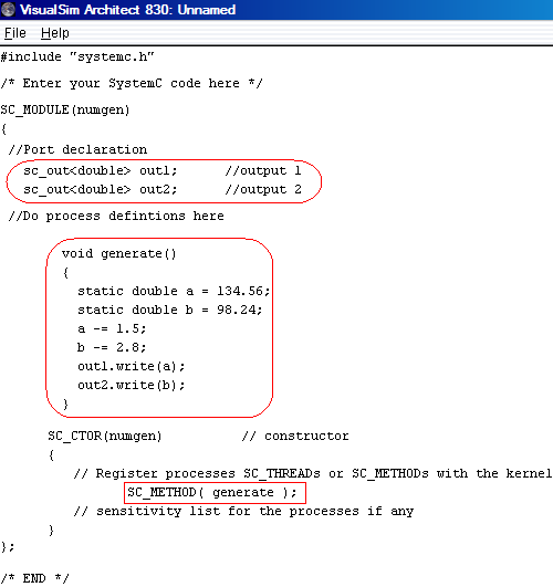
The code after adding the process related code (inside the red color box) is shown in the Figure. Intention is to help the user start writing their process related code straightaway. You notice that the name of the SC_MODULE (numgen) comes from the parameter SC_Module_Name of the SC_Module Interface block.
The ‘numgen’ SC_MODULE consists of two output ports of type “double”. Hence it is required to create the same here.

Figure 6. Configure ports for SC_Module block
If the type is not supported, an Error Message window is displayed. Refer Figure 7 in Creating a simple NAND gate.
We recommend to complete the settings for the C compiler in the section, (Only for the first time) before this section in order to obtain the full functionality of the SystemC blockset.
After the parameters and the ports of the SC_Module Block are configured, it is ready to export the SystemC code to VisualSim and compile them. Click the GUI menu button Interface > Generate Wrapper as shown in Figure 8 to export SystemC code into VisualSim.
Now click the GUI menu button Interface > Compile Wrapper to compile the SystemC code. Successful compilation of Stage 1, Stage 2, Numgen, and Stage 3 are displayed one after another. Click Ok to proceed to the next stage. Success message of numgen is as follows:

Figure 7. Success Message Window
When the compilation process fails, you get the following error message:
Figure 8. Error Message
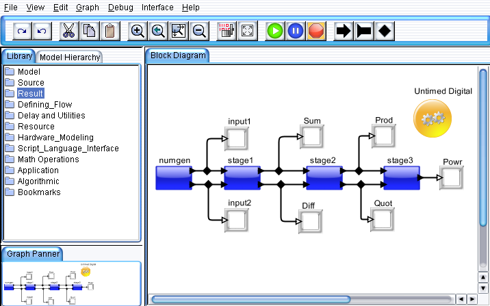
Now we create the other SystemC modules or blocks of the pipeline model in the similar fashion and connect them all as shown in the Figure 9.
Drag the Text_Display (Non-Buffered) block from Results > TextDisplay.
Next, we need to configure SC_Sim and Digital Simulator. Set the Digital->stopTime = 1.0. For the SC_Sim, set the Time_base=SC_NS, Stop_Time=1000.0, and timeResolution=1.0. This means that the SystemC and VisualSim synchronize every 1 ns (timeResolution). The SystemC runs for 1000 ns. VisualSIm can however run for much longer than the SystemC time period.
Press Ctrl + Left mouse click to create the relations to connect the Text_Display (Non-Buffered). It is also appropriate for the user to rename the blocks to the name of the SystemC SC_Module or something similar to help one understand their functionality as shown below.

Figure 9. Pipeline Model
Now click the “Run” button in the IDE or press Ctrl+R to execute the model.
The PIPE example model shown in Figure 9 is located under demo/Interfaces/SystemC/PIPE directory of the VisualSim Install.
Right click on any of the SC_Module blocks of the pipeline model and choose “Open Block” menu item to look at the SystemC code of the block.
If you notice the source code
for this example of SystemC Class Library is available in the directory:
VisualSim\simulators\SystemC\Win\systemc-2.2.0\examples\sysc\pipe.
You get two more additional files (main.cpp & display.cpp) to map the ports or connect all the stages of the pipeline and a SC_MODULE code to display the output value respectively. One need not require those codes to create the model using the VisualSim SystemC Interface blocks as we provide all possible utilities or blocks to develop the model in a faster track. Apart from that, the scope of flexibility is maximum as one could graphically modify the order they require without modifying or writing any code.
Also if you notice closely, it requires a considerable amount time for someone to trace the intermediate values or results that is the output of each stage of the pipeline model. That is one need to connect the ports of their SC_MODULE to the ports of the ‘display’ like SC_MODULE every time they require. This is not only tedious but also time consuming.
Apart from all the advantages, one could see their model execution graphically helping them to understand their flow and validate the results at any or every point of the simulation.
This helps one to create not only a flawless system but also a fine tuned system quickly.