Creating a simple NAND Gate
Let us focus on how to model the NAND gate in VisualSim. A NAND gate is a combinational circuit. Its output is purely a function of the values at the input. It has no memory, and requires no clock. For this reason, the model can use the simplest kind of SystemC process, an SC_METHOD.
We assume that you are already familiar with the SystemC and its code syntax.
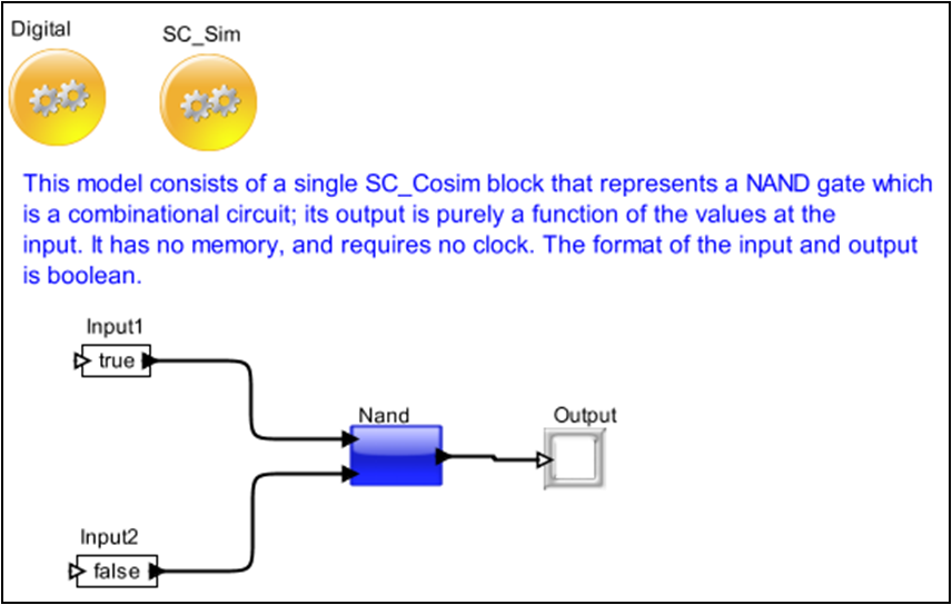
The example model shown in Figure 1 is located under demo/Interfaces/SystemC/Nand directory of the VisualSim Install. This model uses a SC_Cosim block, which has two inputs and one output.

Figure 1. Nand model
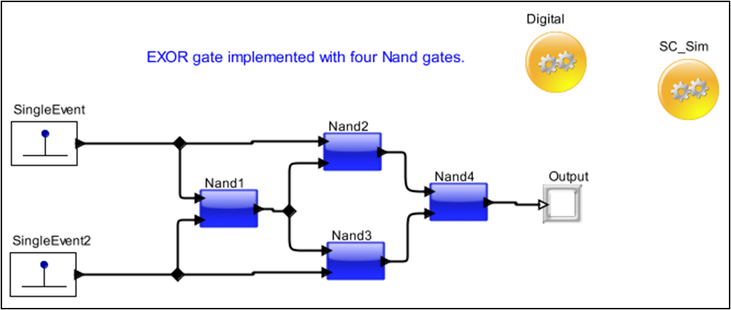
The design consists of an EXOR gate implemented with four NAND gates. It is important to note that this is not a typical design style. But it is very simple to understand. The design is as follows:
Figure 2. Exor Design
A single SC_Cosim block is used to represent a SC_MODULE in SystemC.
Here is the code for the NAND gate, in file nand2.h. To view the following code, right click the Nand block in the model and select Open Block or press Ctrl + L.
#include "systemc.h"
SC_MODULE(Nand) // declare nand2 sc_module
{
sc_in<bool> input1, input2; // input signal ports
sc_out<bool> F; // output signal ports
void do_nand2() // a C++ function
{
F.write( !(input1.read() && input2.read()) );
}
SC_CTOR(Nand) // constructor for nand2
{
SC_METHOD(do_nand2); // register do_nand2 with kernel
sensitive << input1 << input2; // sensitivity list
}
};
This section explains as to how to use and configure the SC_Cosim to export your SystemC code in VisualSim. The SC_Cosim block is located in the Script_Language_Interface Library under SystemC. The block can be placed on the canvas in the same way as any other Java blocks. Once the SC_Cosim has been placed on the canvas, the block needs to be configured. The user must also place the SC_Sim, located in Hardware Languages > SystemC folder. The SC_Sim provides the initiatize and setup information for SystemC.
Right click SC_Cosim block and choose Customize > Configure menu item to configure the block parameters.
Figure 3. Configuring the SC_Cosim block
The NAND gate SC_MODULE consists of two input ports and one output port all of type boolean (refer the nand2.h). Hence it is appropriate to create the same here.

Figure 4. Configure ports for SC_Cosim block

Figure 5. Configure ports for SC_Cosim block
Now type the name of the port in the text box with caption “Name” and then enable input or output but not multiport as it is not applicable to this block. Enter the “SystemC Datatype” for the port in the text box with caption “Remote Type”. In case of ‘bool’ type, specify it as ‘boolean’.

Figure 6. Configure ports for SC_Cosim block
Figure 7: Sample Error Message for incorrect data type at the interface
We recommend to complete the settings for the C compiler (Only for the first time) before this section in-order to obtain the full functionality of the SystemC blockset.
Once the parameters and the ports of the SC_Cosim block are configured, it is ready to export the System_C code to VisualSim and compile them. Click Interface > Generate Wrapper as shown in the following figure to export SystemC code into VisualSim.
Figure 8: Menu Bar View to Select Generator
Now click Interface > Compile Wrapper to compile the SystemC code. Successful compilation displays a message as below:

Figure 9. Success Message Window
When the compilation process fails, you get the following warning message:

Figure 10. Error Message Window
After the SystemC code is exported into VisualSim, it is ready to simulate them to get the results.
Our example design consists of four NAND gates implementing a EXOR gate. Hence we need to create three more instances of the NAND gate and it is easily done by making a copy of the block with Ctrl+C, pasting it to the Editor space with Ctrl+V and then connecting the blocks as shown in the Figure11.
The Text_Display(Non-buffered) block can be dragged on to the canvas on the right from the Result library under Text. Similarly the “Const” input block can be obtained from the Ful Library > Math Operations > Math and Trig . Control-click to create the relations from the toolbar.
Connect all the blocks as shown in Figure 11 and then add a Digital Simulator (located under “ModelSetup) and a SC_Sim (located under "Full Library > Hardware Languages > SystemC).
Now you need to configure the values for the Digital Simulation and SC_Sim. For the Digital, set the stopTime = 1.0e-6. For the SC_Sim, set the StopTime = 100.0, Time_Base = SC_NS and timeResolution=1.0.
Click the Run button in the IDE or press Ctrl+R to execute the model.

Figure 11. Exor Model
Let us look at another Example Model - PIPE.