Alternate Bit Protocol (Protocol Modeling with FSMs and Digital Simulator)
Open this model in VisualSim from the following location:
$VS/doc/Training_Material/FSM/ABP/ABP.xml
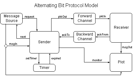
This model demonstrates the use of the Discrete Event (DE) simulator and hierarchical finite state machines (FSM's) to model the Alternating Bit Protocol (ABP). ABP [2] is a simple mechanism for achieving reliable, ordered delivery of messages over channels with unreliable delivery and variable delay. Figure 1 shows the block diagram of the protocol and Figure 2 shows the top level of the model, which operates in the Digital simulator, is shown below with a panel that controls the execution of the model.

Figure 1: Block Diagram of the Alternating Bit Protocol
The components in the model include:
Message Source: This is a DE atomic actor with a parameter MaxDelay. After execution starts, it waits for a random delay uniformly distributed between 0 and MaxDelay, and then sends a request to the sender. When it receives a next from the sender, it again waits for a random delay uniformly distributed between 0 and MaxDelay, and then sends a new msgIn with sequence number increased by one to the sender. In this demo, MaxDelay is set to 0.5.
Timer: The timer has an input setTimer of type DoubleToken. The value of the input token gives the delay before the next timer expires. The timer is reset every time it gets an input token.
Channel: The channel models an unreliable connection in a packet switching network. It queues the input packets, drops and delays the packets randomly. A channel has three parameters: DropRate, MinDelay, and MaxDelay. DropRate is the probability that an input packet gets dropped. Packet delay in the channel is uniformly distributed between MinDelay and MaxDelay.
Plot: The plot shows the result of data transmission. In the plot, the red data gives the sequence number of the messages coming out from the receiver. The blue data gives the sequence number of the messages going to the sender. The third data is the "alternating bit" that the protocol uses to number the packets going through the channel.
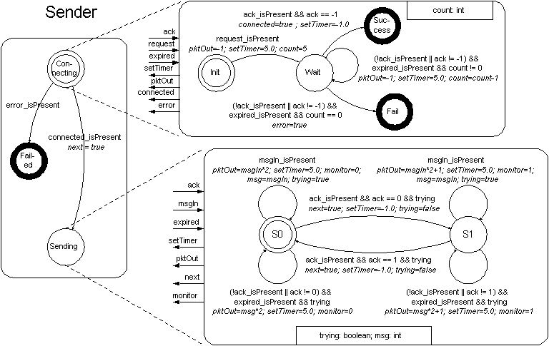
Sender: The sender implements the sending part of ABP and is shown in Figure 4.

Figure 3: ABP Sender protocol
The top level Hierarchical FSM implementation is a 3-state FSM. Figure 5 shows the Sender implementation.
Figure 4: Implementation of the top-level ABP Protocol
The top level FSM starts in the Connecting state. This state refines to the following FSM:
Figure 5: Implementation of the Sender- Connecting State
This FSM starts in the Init state. When a request from the message source is received, the FSM sends a special packet (with sequence number -1) to the receiver, sets the timer, and goes to the Wait state. If there is no acknowledgment from the receiver before the timer expires, the FSM sends the special packet again, remains in the Wait state, and waits for the next timeout or acknowledgment from the receiver. If an acknowledgment is not received within five tries, the FSM goes to the Fail state and sends an error event to the top level FSM. Otherwise the FSM goes to the Success state and sends a connected event to the top level.
If connection fails, the top level FSM goes to the Failed state and stops. Otherwise it sends a next event to the message source, and goes to the Sending state, which refines to the following FSM:
Figure 6: Implementation of the Sender- Sending State
This FSM starts in state S0. When a message from the message source is received, the FSM stays in its current state, tags the message with an additional bit (0 in state S0, 1 in S1, hence the term "alternating bit") to form a packet, and tries repeatedly to send the packet until the receiver acknowledges. When the receiver acknowledges, the FSM sends a next event to the message source, and goes to the other state.
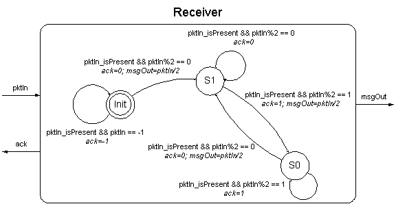
Receiver: The receiver is a flat FSM as shown below:

Figure 7: Block Diagram of the Receiving State
Figure 8: Implementation of the Receiving State
The receiver starts in state Init. In this state, the FSM acknowledges the special packet (with sequence number -1) that the sender sends in trying to establish connection. When a packet tagged with bit 0 is received, the FSM acknowledges the packet, sends the message in the packet to msgOut, then goes to state S1. In state S1, the FSM acknowledges any packet tagged with bit 0. When a packet tagged with bit 1 is received, the FSM acknowledges the packet, sends the message in the packet to msgOut, then goes to state S0. In state S0, the FSM acknowledges any packet tagged with bit 1 while waiting for a packet tagged with bit 0.
Figure 9: Simulation Parameters and Results of the ABP model
J. Walrand, and P. Varaiya, ``High-Performance Communication Networks,'' pages 69-72, Morgan Kaufmann Publishers, Inc., 1996.