Interfaces and Buses / Networking / NODE
Code File Location: VisualSim/Actor/lib/NODE


[1] The
'Routing_Table' Block provides information for the network,
including "Routing_Algorithm", "Routing_Algorithm_Cost", and
"Routing_Latencies". The connectivity information can be in a
Database block with the linking name matching the Routing_Table name or
in a file selected in the Routing_File_Name setting. There can be
more than
one Routing_Table/Database pair in a network model.
[2] The
Node block uses a Connectionless Routing and the data structures are
passed from Node block to Node block without connections or physical
wires.
[3] Routing Table Format:
The Routing Table Database block must have the Linking_Name match the Routing_Table_Name parameter of this block. The format of the Database entries, is shown below:
ID
Source_Node Destination_Node Distance Speed_Mbps
Duplex ;
0 Node_1
Node_2
10.0
100.0
true ;
1 Node_2
Gateway_3
10.0 100.0
true ;
2 Gateway_3
Node_2
10.0
100.0
true ;
3 Node_2
Node_1
10.0
100.0
true ;
Note: There must be Tabs or spaces between each of the columns. The first row must contain the names of the columns. Each row corresponds to one Direct connection. There must be a space before the ;.
All input and output links to a NODE are described separately. This allows the user to allocate different bandwidths in each direction and to allow users to disable a single link in a single direction. The Add and remove of link is accomplished by the NODE_Master block. Please refer to NODE_Master block documentation for further details.
Users can obtain statistics
for each NODE block from the NODE_Master block or through the use of a
RegEx function. The statistics output
looks like:
{"Source", "Destination", "Mbps",
"Min_Utilization", "Mean_Utilization", "StDev_Utilization",
"Max_Utilization"}
, {"Node_1", "Node_2", "0.0", "0.0", "0.0",
"0.0", "0.0"}
,
{"Node_1", "Node_3", "156309.67", "0.00137",
"0.00156", "1.612977E-4", "0.00319000032"}
The generated statistics are for each link and
contain the
Mbps and, min, mean, stdev and max of the link utilization. The
RegEx
function allows one to collect all of the
statistics for the entire routing table domain,
using the following expression, assuming the Routing_Table name is "RT":
getBlockStatus("RT",
"stats", -1) // Generates the statistics and resets the
statistics for all links in Routing Table- "RT"
getBlockStatus("RT", "stats", 0) // Generates statistics for all links in Routing Table- "RT"
getBlockStatus("RT", "stats", 1)
// Returns connectivity table for routing table domain
getRoutingTableHop("RT","Node_1","Node_2") //
Returns the next node hop, if there is no hop, then return "none"
RT represents the name of the Routing Table associated with this NODE block.
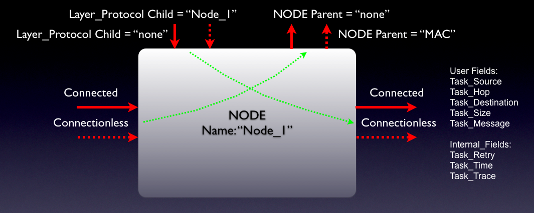
There are two types of fields- one are the user input and the others are used internally. The data structure used must contain these fields or a error will be generated. The user fields are:
Task_Source: Message Source Node. This is not modified by this block.
Task_Hop: Next Node in the data transfer. The user will set it to the current node. This block will modify the Task_Hop field based on the content of the Routing Table. This field is modified.
Task_Destination: Final Destination Node Name. This block uses this field to determine what the next Hop is. This field is not updated.
Task_Size: Size in Bytes of the data, excluding Header and Trailers. The Node block uses this field to compute the link transfer delay time. This field is not modified.
Task_ID: First Layer_Protocol block encountered will generated a sequence number. This is a single sequence is for all Layers in all the Nodes. When a new packets arrives a Layer for the first time, the sequence number is incremented. For the Task_ID to be updated, the entering Task_ID=-1. This is field is not used in the Node block. This field is not modified.
Network_Message: Currently used only for identifying Retry_, Multicast and Drop_Packet. The Node uses this field for Retry and Drop_Packet. If the field starts with Retry, the Node will not send this packet to the layers above. The Node will send this packet to the next Node in the flow. If this is the original Source Node, it will send it to the upper Layer. If the Task_Hop cannot be found to the Task_Destination, then it sets the Network_Message to "Drop_Packet" and returns it back to the Task_Source. If the Task_Source is the current Node, it drops the packet. This field is modified by this block.
The Internal Fields are as follows:
Task_Retry: Number of retries for this packet. When this number exceeds the threshold, the packet is dropped by updating Network_Message="Drop_Packet", and then returned to the top Layer_Protocol of the Source_Node. This block ignores this fields. This field is not modified.
Task_Time: The Node computes the latency for the Packet to transfer across the network and palces the value in this field. This is also used to calculate utilization in the Node blocks. This field is modified.
Task_Trace: This is a array of Node names that this packet has encountered. The Node block appends it's name to this field. This field is modified.
Task_Overhead: This block will maintain the amount of overhead bytes accumulated. Subtracting this from Task_Size will give the original data size. This is not used by this block. This field is not modified.
Network_Basic Demo Model. This shows a basic connectionless network, the Routing Table reference and the path definition in the Database block.
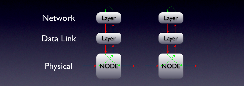
Retry Network Demo Model. This shows a Connected Network with the layers of the OSI stack referenced.
Gateway_Connected Demo Model. This shows the use of the Node as a Gateway.
Multi_Network_w_Intermediate_Gateway Demo Model. This model has a intermediate of Gateway nodes.
Gateway_w_Diff_Return_Model Demo Model. In this model, the forward and return directions use a different Gateway Node.
Two_Networks_w_Gateways Demo Model. This shows two Gateways between two networks.
Mulitcast Demo model showing the use of the Multicast function along with the Node block.
Parameter |
Explanation |
Type |
Example |
|
Node_Name |
Name of this node. All nodes should have unique names to prevent routing conflicts. The Gateway node must always start with "Gateway".
|
String |
"Node_1" |
|
Routing_Table_Name |
Name of Routing Table
|
String |
"RT" |
|
Gateway_Node |
If checked, this node is designated as a gateway node to another subnet, or to a gateway subnet. |
Boolean |
Default, unchecked |
Port |
Explanation |
Type |
|
node_input |
This is the input connection from the traffic generator or the input from the Layer above. This will be connected to a Traffic block or to the Layer_Protocol block. |
General |
|
node_output |
This port is used to send
the
data to the upper layers. If there are Layer_Protocol blocks,
then this port can be connected directly to the "ds_up_input" port. |
General |
Created with the Personal Edition of HelpNDoc: Full-featured EPub generator