Multiplexer Model
The following section explains the
creation of Multiplexer Verilog model in VisualSim. A Model is 2:1
Multiplexer to implement using Gate level. It is constructed using two
And-gate, one Not-gate, and one Or-gate. The Output equation is
Q=A.S'+B.S.
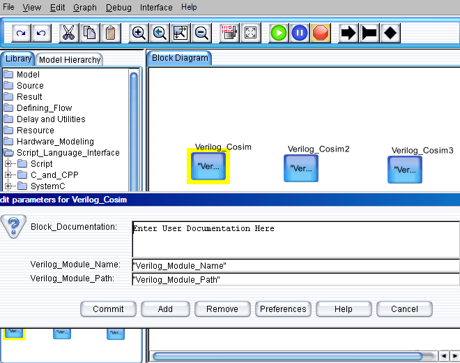
- Drag three Verilog_Cosim blocks from Full Library > Script_Language_Interface > Verilog to the editor space.

Figure 1. Multiplexer Model
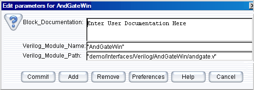
- Right click on the actor and select Configure Arguments. Configure the parameter values as shown in the figure. The parameters are as follows:
Configuring for Andgate Block
- The Verilog_Module_Name is the model name in Verilog.
For example, ”AndGate”.
- The Verilog_Module_Path is the path to the Verilog source files (*.v).
For example, “D:/VisualSim/VS930/demo/interfaces/Verilog/AndGate/andgate.v”.
Here the “*.v” file name should be same as the Verilog module name in the user
Verilog code.

Figure 2. Configuring the parameters for Verilog_Cosim
Configuration for Orgate Block
- The Verilog_Module_Name is the model name in Verilog.
For example, ”OrGate”.
- The Verilog_Module_Path is the path to the Verilog source files (*.v).
For example, “D:/VisualSim/VS930/demo/Interfaces/Verilog/OrGate/orgate.v”.
Here the “*.v” file name should be same as the Verilog module name in the user Verilog code.

Figure 3. Configure ports for OrGateWin
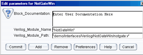
Configuration for Notgate Block
- The Verilog_Module_Name is the model name in Verilog.
For example, ”NotGate”.
- The Verilog_Module_Path is the path to the Verilog source files (*.v).
For example, “D:/VisualSim/VS930/demo/Interfaces/Verilog/NotGate/notgate.v”.
Here the “*.v” file name should be same as the Verilog module name in the user Verilog code.

Figure 4. Configuring the parameters for NotGateWin
- Now save the model before code generation.
- Click Interface > Generate Wrapper for code generation.
- Click Interface > Compiler Wrapper for code compilation of the source files.

Figure 5. Menu Bar View to Select Generator
- Configure the ports in the Verilog_Cosim Block:
- Select the context menu of the Verilog_Cosim and select Customize > Ports.
- Configure the input /output ports and type of the ports in the Verilog_Cosim block.

Figure 6. Configure ports for the AndGate

Figure 7. Configure ports for the NotGate
- A new folder named
“AndGate”, ”OrGate”, and “MuxGate” is automatically created under
Verilog directory, if it does not exist already. Otherwise it overwrites
the existing generated files with the new files.
Successful compilation of the
source files creates Jni<Verilog_Module_Name> .dll file under
the blocks directory. The file extension “. Dll” indicates that the file is
a dynamic link library (dll).
Note:
Open the “vsout.txt” file under the libraryDirectory to verify the
errors that could have caused any unsuccessful compilation process.
These could help to correct any mistakes in the interface code.
- The blocks directory has been provided under UserNativeC directory to hold “. Dll” files, which are in the PATH.
- Drag the
Text_Display (Non-buffered) from the Result - Text. Similarly, the
“Const” input block from the Math Operations > Math and Trig.
Control-click to create the relations from the toolbar.
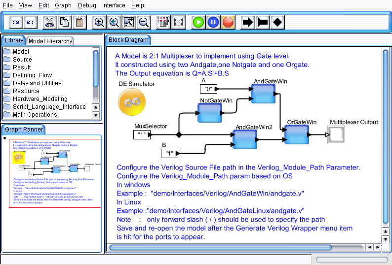
- Connect all the blocks as shown in the Figure 8.
- Add a Digital simulator (located under Model > Simulator). Double click and change the number of iterations from 0 to 1.
- To run multiplexer model, click the run button in the IDE or Press Ctrl+R.

Figure 8. Multiplexer Model


