Block Name: FC_Switch
Code Location: VisualSim/actor/arch/Buses/FibreChannel/FC_Switch
Table of Content
Description
Flow Diagram
Flow Control
Datastructure Fields
Block Dependency
Examples
Parameters
Description
The purpose of switch block is to support fragmentation, assembly and quick data movement. (Note: If you are looking Fibre Channel Switch having more than 16 Ports, then please use "FC_Switch_96_Nodes" block. This block supports 96 N_Port connections to a single Switch)
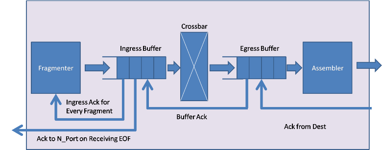
Fibre Channel Switch will Fragment the incoming frame to the fragment size and forward it to ingress buffer. Each fragment is acknowledged by the Ingress Buffer before the next fragment is sent out. The Fibre Channel Switch can support up to 16 connections. There is a unique fragmenter block per port. Ingress buffer has a dedicated queue for each connections and forwards transactions from respective queue to Egress buffer based on the flow control. Class1 messages will be sent out as soon as the egress buffer is available, however class2 and class3 implements buffer-to-buffer flow control. Each port will have a dedicated counter that monitors the number of transactions sent. This counter is used to test for available buffer space in the Egress Buffer. For every transaction sent, counter will be incremented by one. For class 2 and Class 3, ingress buffer will wait for an acknowledgement from the egress buffer. On receiving the Acknowledgement counter will be decremented by one for the corresponding port.
Crossbar switch has 16*16 dedicated channels to make sure that there are no collisions. The Crossbar has a delay associated with it. The delay is based on the fragment size and Switch_Speed_MHz.
Egress Buffer acknowledges every fragment sent from ingress buffer. Once all fragments are received at the Egress port, the fragments will be assembled into the original transaction. Egress receives the Ack from the Ingress of the next switch or the Destination N_Port. Once it receives Ack from next switch or destination N_Port, it transmits the next transaction
Flow Diagram

Flow Control
Flow control is dependent upon the service classes. Class 1 Frames use end-to-end flow control, class 3 uses only buffer-to-buffer, class 2 Frames use both types of flow control. Flow Control is managed by the Source and Destination ports using credit counters.
Class 1 is a service which provides dedicated connections, in effect providing the equivalent of a dedicated physical connection.
Class 2 is a Frame-switched, connectionless service that allows bandwidth to be shared by multiplexing Frames from multiple sources onto the same channel or channels.
Class 3 service is identical to Class 2, except that the Frame delivery is not confirmed. (Flow control is managed only on buffer level)
Data Structure Fields
FC_Switch requires few mandatory fields included in the A_Source, A_Destination, A_Command ("Read"/"Write"), A_Message (initialized with Class1, Class2 or Class3), A_Bytes, A_Bytes_Remaining, A_Bytes_Sent are the required fields.
Example:
input.A_Source = "Device_1"
input.A_Destination = "Device_9"
input.A_Command = "Write" /*"Write"*/
input.A_Message = "Class1" /*"Class2" or "Class3" */
input.A_Response = "false"
input.A_Bytes = 15000 /* Bytes */
input.A_Bytes_Sent = 2112
input.A_Bytes_Remaining = 12888
A_Sourcce field represents the name of Source device, A_Destination field represents Destination device name, A_Command is to identify whether the transaction is a Read/Write transfer. A_Message helps one to set type of service, please note that the Field values can be either "Class1", "Class2" or "Class3". Purpose of A_Response field is to indentify if a transaction is a response from Destination device or a transaction from Source device. A_Bytes field has total size of the packet, A_Bytes_Sent field get updated with Fragment Size plus Overhead Bytes in Fibre Channel Switch. A_Bytes_Remaining has the details about remaining fragment size waiting for transmission.
Block Dependency
FC_Switch block requires FC_N_Node, FC_Link, DeviceInterface (optional), FC_Config blocks instantiated in the model.
Examples
1. FC with Single Switch
2. FC with Two Switches
2. FC with Multi Switch
Parameters
Name
|
Type
|
Description
|
Switch_Name
|
String
Ex: “FC_Fabric_1”
|
Name of Fibre Channel Switch
|
Ingress_Buffer_Size
|
Integer
Ex: 512
|
Size of Ingress Buffer at Each Port
|
Egress_Buffer_Size
|
Integer
Ex: 512
|
Size of Egress Buffer at Each Port
|
Architecture_Name
|
String
Ex: "Architecture_1"
|
Name of Arch_Setup
|
Switch_Speed_MHz
|
Double
Ex: 800
|
Speed of Crossbar switch
|
Fragment_Size
|
Integer
2112
|
Size of Frame Fragment
|
Overhead_Bytes
|
Integer
Ex: 30
|
Overhead Bytes
|
Enable_Debug
|
Boolean
Ex: true
|
Enable or Disable Debug Message
|
Switch_ID
|
Integer
Ex: 1
|
Unique Identifier for Switch
|
|