Constructing FSM Based Models
We will build the same model from the Pre-built tutorial called bouncing ball.
The model is located in:
$VS/doc/Training_Material/FSM/BouncingBall.xml
A FSM-Hierarchical is a FSM component in a larger system model. You can create a Hierarchical FSM by dragging a FSM-Hierarchical in from the FSM library. By default, it has no ports. To make it useful, you will need to add ports. The mechanism for doing that is identical to adding ports to a composite model. Figure 1-1 shows a top-level continuous-time model with a single FSM-Hierarchical that has been renamed Ball Model. Three output ports have been added to that modal model, but only the top one is used. It gives the vertical distance of the ball from the surface on which it bounces.

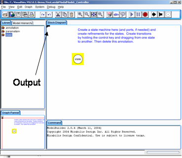
Figure 1: Inside of a new modal model that has had a single output port added
If you create a new FSM-Hierarchical by dragging it in from the FSM library, create an output port and name it output, and then look inside, you will get an FSM editor like that shown in figure 1.
Note that the output port is (regrettably) located at the upper left, and is only partially visible. You may want to move the port to a more reasonable location (where it is visible).
The output port that you created is in fact indicated in the state machine as being both an output and input port. The reason for this is that guards in the state machine can refer to output values that are produced on this port by refinements. In addition, the output actions of a transition can assign an output value to this port. Hence, the port is, in fact, both an output and input for the state machine.

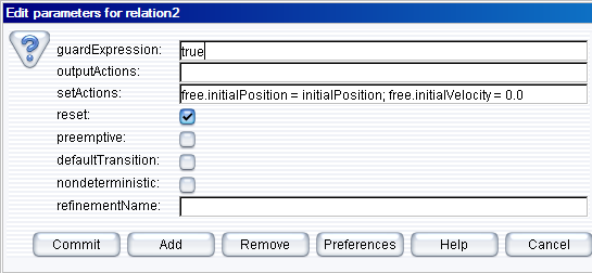
Figure 2: Transition dialog for the transition from init to free in the Pre-Built Model
To create a state machine like that in figure 1-2, drag in states (white circles), or click on the state icon in the toolbar. You can rename these states by right clicking on them and selecting "Customize Name". Choose names that are pertinent to your application. In figure 1-2, there is an init state for initialization, a free state for when the ball is in the air, and a stop state for when the ball is no longer bouncing. You must specify the initial state of the FSM by right clicking on the background of the FSM Editor, selecting “Edit Parameters”, and specifying an initial state name, as shown in figure 1-3. In that figure, the initial state is named init.
To create transitions, you must hold the control button on the keyboard while clicking and dragging from one state to the next (a transition can also go back to the same state). The handles on the transition can be used to customize its curvature and orientation. Double clicking on the transition (or right clicking and selecting “Configure”) allows you to configure the transition. The dialog for the transition from init to free is shown in figure 1-8. In that dialog, we see the following:
The “free” in these expressions refers to the mode refinement in the free state. Thus, free.initialPosition is a parameter of that mode refinement. Here, its value is assigned to the value of the parameter initialPosition. The parameter free.initialVelocity is set to zero.
A state may have several outgoing transitions. However, it is up to the model builder to ensure that at no time does more than one guard on these transitions evaluate to true. In other words, VisualSim does not allow non-deterministic state machines, and will throw an exception if it encounters one.
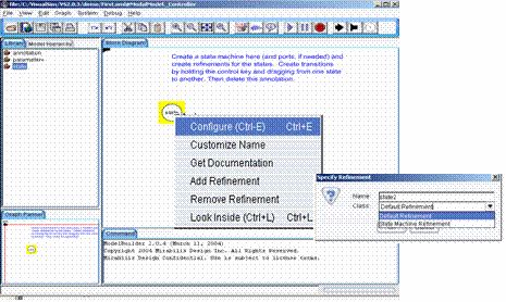
Both states and transitions can have refinements. To create a refinement, right click on the state or transition, and select “Add Refinement.” You will see a dialog like that in figure 3. As shown in the figure, you will be offered the alternatives of a “Default Refinement” or a “State Machine Refinement.” The first of these provides a block diagram model as the refinement. The second provides another finite state machine as the refinement. In the former case (the default), a blank refinement model will open, as shown in the figure. As before, the output port will appear in an inconvenient location. You will almost certainly want to move it to a more convenient location. You will have to create a director in the refinement. The modal model will not operate without a director in the refinement.
You can also create refinements for transitions, but these have somewhat different behavior. They will execute exactly once when the transition is taken. For this reason, only certain directors make sense in such refinements. The most commonly useful is the Untimed Digital director. Such refinements are typically used to perform arithmetic computations that are too elaborate to be conveniently specified as an action on the transition.
Once you have created a refinement, you can look inside a state or transition. For the bouncing ball example, the refinement of the free state is shown in figure 5 of Pre-Built Tutorial. This model exhibits certain key properties of refinements:

Figure 3: Adding a refinement to a state
The behavior of a refinement is simple. When the modal model is executed, the following sequence of events occurs:
There is a subtle distinction between the output actions and the set actions. The intent of these two fields on the transition is that output actions are used to define the values of output ports, while set actions are used to define state variables in the refinements of the destination modes. The reason that these two actions are separated is that while solving a continuous-time system of equations, the solver may speculatively execute models at certain time steps before it is sure what the next time step will be. The output actions make no permanent changes to the state of the system, and hence can be executed during this speculative phase. The set actions, however, make permanent changes to the state variables of the destination refinements, and hence are not executed during the speculative phase.