HardwareDevices / BusArbiter
Block Name: BusArbiter
Code File Location: VisualSim/actor/lib/bus/Linear_Controller
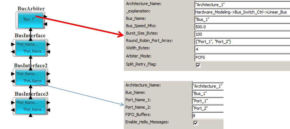
The BusArbiter block is the Arbiter for a Linear Bus. The Linear bus is a shared bus topology with a arbiter. The devices are connected to the ports of the BusInterface blocks. The connectivity betwene the BusInterface and Linear_Bus is shown below.

Examples of Buses created using this block include AMBA (AHB and APB) and PCI. Custom and proprietary shared bus topologies can also be created using this block.
The block parameters manages the operation of the block. The Architecture_Name is the name of the ArchitectureSetup block that maintains the routing, debugging and statistics information.
The Arbiter_Mode supports First Come-First Server, Round-Robin and Custom. The buffers on the input Linear Ports are priority-based and will reorder on the arrival of each new transaction. The first transaction in each port queue is sent to the Controller and scheduled at the Controller in the order of arrival. To customize the arbitration algorithm, the Arbiter_Mode is set to Custom and the logic is attached to the input1/output1 ports of this BusArbiter. The BusArbiter block has a single non-Priority Queue. All the BusInterface have equal access to the Arbiter and are equidistant. The content of this Queue can be accessed from the external Custom logic using the RegEx language. For more details about the usage, view the demo model and refer to the Advanced Modeling Documentation. The BusArbiter requires specific fields in the Data Structure to operate correctly. Refer to the demonstration examples in Pre-Built Models->Using Hardware Architecture Blocks->ReadBus.xml and WriteBus.xml.

The devices connected to the Linear_port can be a Processor, DMA, Memory Controller, Cache, DRAM, and custom device. To connect the custom device, use the Hardware->Core_Architecture->I_O block at the Linear_Port interface.
To illustrate the usage, look at the following Examples in the BDE.
Write Delay: The delays in this block are the queuing at the BusInterface, one address/control cycle and the transfer of the data. The data transfer time is the A_Bytes/Bus_Speed. If there is a acknowledgement, then the delay is simply one cycle across the bus.
Read Delay:The delay in this block are the queuing at the Linear_Port, followed by one address/control cycle. When the data returns from the Destination/Slave device, there is one address/control cycle, followed by the data transfer. The data transfer time is the A_Bytes/Bus_Speed.
The following fields are required by the Linear Bus, including AHB bus mode. If any of these fields are missing in the data structure, an exception will be reported.
The standard Processor_DS data structure also contains these fields:
A_Source, A_Hop, A_Destination, A_Bytes, A_Bytes_Remaining, A_Bytes_Sent, A_Command, A_Task_Flag, A_Status, A_Prefetch and A_Interrupt.
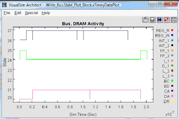
A Write transaction proceeds as follows.

Figure 1. Timing Diagram – Write Transaction
The following table shows an example of a Write activity:
List of Fields |
Input from Master |
Output to Slave (Burst 1) |
Output to Slave (All other Bursts) |
A_Bytes |
Request Data Size |
Value unchanged |
Value unchanged |
A_Bytes_Remaining |
Request Data Size -Master Width |
Request Data Size -Bus Burst Width |
Request Data Size -2* Bus Burst Width |
A_Bytes_Sent |
Master Width |
Bus Burst Width |
Bus Burst Width |
A_Destination |
Final Destination |
No Change |
No Change |
A_Source |
Original Source |
No Change |
No Change |
A_First_Word |
TRUE |
No Change |
No Change |
A_Interrupt (Opt.) |
FALSE |
No Change |
No Change |
A_Prefetch (Opt.) |
FALSE |
No Change |
No Change |
A_Status |
Used internally by Linear Bus. Set to Slave port name |
Set to Slave port name + Append "_" |
Set to Slave port name + Append "_" |
A_Hop |
Slave side port name |
Next Bus or Destination if direct connect |
Next Bus or Destination if direct connect |
A_Task_Flag |
Don’t care |
No Change |
No Change |
A_Command |
Write |
No Change |
No Change |
Table 1. Write Activity
The following table shows an example of a Write Response:
List of Fields |
Input from Slave |
Output to Master |
A_Bytes |
Request Data Size |
Value unchanged |
A_Bytes_Remaining |
Request Data Size |
Request Size - Bus Width |
A_Bytes_Sent |
0 |
Bus Width |
A_Destination |
Final Destination |
No Change |
A_Source |
Original Source |
No Change |
A_First_Word |
TRUE |
No Change |
A_Interrupt (Opt.) |
FALSE |
No Change |
A_Prefetch (Opt.) |
FALSE |
No Change |
A_Status |
This is used internally by the Linear Bus. This is set to Master port name |
Append _ to_Name |
A_Hop |
Don’t Care |
Next Bus or Destination if direct connect |
A_Task_Flag |
Don’t Care |
Don’t Care |
A_Command |
Read. Can have any suffix |
Unchanged |
Table 2. Write Response
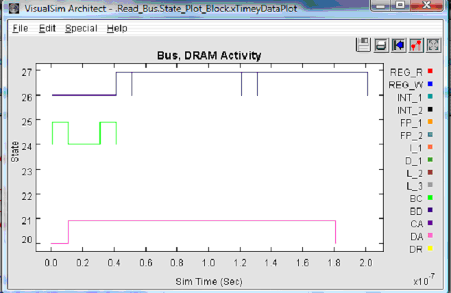
A Read transaction proceeds as follows.
Read Request Transaction:
The following table shows an example of a Read Request Transaction:
List of Fields |
Input from Master |
Output to Slave |
A_Bytes |
Request Data Size |
Value unchanged |
A_Bytes_Remaining |
Request Data Size- Master Width |
Request Size - Bus Width |
A_Bytes_Sent |
0 |
Bus Width |
A_Destination |
Final Destination |
No Change |
A_Source |
Original Source |
No Change |
A_First_Word |
TRUE |
No Change |
A_Interrupt (Opt.) |
FALSE |
No Change |
A_Prefetch (Opt.) |
FALSE |
No Change |
A_Status |
This is used internally by the Linear Bus. This is set to Slave port name |
Append _ to_Name |
A_Hop |
Don’t Care |
Next Bus or Destination if direct connect |
A_Task_Flag |
Don’t Care |
Don’t Care |
A_Command |
Read. Can have any suffix |
Unchanged |
Table 3. Read Request Transaction
Read Transaction- Response:
The following table shows an example of a Read Transaction- Response:
List of Fields |
Input from Slave |
Output to Master (End of all Bursts) |
Output to Master (All other Bursts |
A_Bytes |
Request Data Size |
Value unchanged |
Value unchanged |
A_Bytes_Remaining |
Request Data Size- Slave Width |
Request Data Size -Bus Burst Width |
Request Data Size -2* Bus Burst Width |
A_Bytes_Sent |
Slave Width |
Bus Burst Width |
Bus Burst Width |
A_Destination |
A_Source (Names flipped from Request. Can be an alternate destination also) |
No Change |
No Change |
A_Source |
A_Destination (Names flipped from above. Can be an alternate destination also.) |
No Change |
No Change |
A_First_Word |
TRUE |
No Change |
No Change |
A_Interrupt (Opt.) |
FALSE |
No Change |
No Change |
A_Prefetch (Opt.) |
FALSE |
No Change |
No Change |
A_Status |
Used internally by Linear Bus. Set to Slave port name. |
Set to Master port name + Append "_" |
Set to Master port name + Append "_" |
A_Hop |
Slave side port name |
Next Bus or Destination if direct connect |
Next Bus or Destination if direct connect |
A_Task_Flag |
Don’t Care |
No Change |
No Change |
A_Command |
Write |
No Change |
No Change |
Table 4. Read Transaction- Response

Figure 2. Timing Diagram – Read Transaction
Typical flow involves first getting the length of the arbiter Queue using the RegEx function.
Then loop through the arbiter Queue to examine each item, depending on the arbitration algorithm.
Next, determine which transaction fragment to transmit. The list of RegEx functions can be viewed by looking at Linear Bus Extensions portion of the RegEx.
The RETRY response works only for Read operations. It currently does not support Write operations. It provides a mechanism for slaves to release the bus when they are unable to supply data for a transfer immediately. The mechanism allows the transfer to finish on the bus and therefore allow a higher-priority master to get access to the bus.
If the Core->Cache or DRAM is used, the block uses the getBlockStatus RegEx to determine the status. For any other Destination, the Bus will check the global memory called Destination Name + "_Status". If the value of the RegEx or this Global Memory is true, the normal transfer occurs. If the value is false, then the Bus will generate a Retry. When a Retry occurs, the arbiter will continue to use the normal priority scheme and therefore only masters having a higher priority will gain access to the bus.
Explanation |
Type |
Example |
|
Architecture_Name |
This is the name of the Architecture_Setup block that this BusArbiter is associated. The Architecture_Setup block maintains the routing table, debugging and statistics collection. |
String |
"Architecture_1" |
Bus_Name |
This is a unique name of this BusArbiter. All the BusInterface associated with this Controller will also have the same name. No other BusArbiter in the model can have the same name. |
String |
"Bus_1" |
Bus_Speed_Mhz |
This is the speed of the Bus in Mhz. |
Double |
500.0 |
Burst_Size_Bytes |
This is the Burst Size on the Bus in bytes. |
Integer |
100 |
Round_Robin_Port_Array |
This is an array with the names of all the ports with the Round Robin order. This is required for the Round-Robin arbiter. |
Sring Array |
{"Port_1", "Port_2"} |
Width_Bytes |
The is the width of the Bus in Bytes. |
Integer |
4 |
Arbiter_Mode |
The Arbiter Mode selection determines the operation of the Bus.The arbitration algorithms are FCFS, RR and Custom. |
Pull-down |
FCFS |
Split_Retry_Flag |
By selecting, the Split and Retry operation is enabled. |
Boolean |
Checkbox |
Explanation |
|
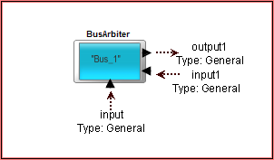
input |
Input Port to the BusArbiter from the BusInterface. |
input1 |
Input Port from the arbitration logic. This is used to return the Data Structure from the Arbiter during the custom mode. |
output1 |
Output Port to the arbitration logic. This is used to send the Data Structure to the Arbiter during the custom mode. |
Created with the Personal Edition of HelpNDoc: Easily create HTML Help documents