Code File Location: VisualSim/actor/arch/Buses/AMBA_AXI_16_X_16
2. Operation
3. Standard internal delay - Read
4. Standard internal delay - Write
6. Model Parameters, Expected Data structure and ports
10. Enabling Power
The AMBA_AXI Bus protocol is targeted at high-performance, high-frequency system designs and includes a number of features that make it suitable for a high-speed sub micron interconnect. The objectives of the AMBA_AXI Bus are to be suitable for high-bandwidth and low-latency designs and enable high-frequency operation without using complex bridges. It meets the interface requirements of a wide range of components and it is suitable for memory controllers with high initial access latency and provide flexibility in the implementation of interconnect architectures.
It can able to establish more than
one outstanding transaction between different master and different slave.
For detailed information on the AXI Bus, refer to $VS/doc/Chapter_8-Bus_Standards.pdf.
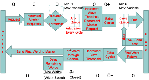
Figure 1. AXI_Read_Flow_Diagram
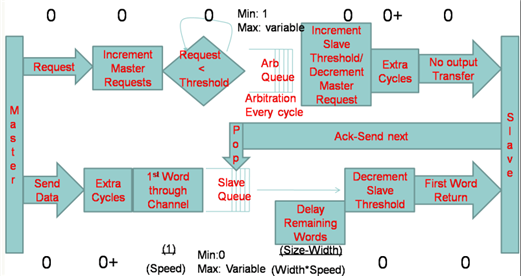
Figure 2. AXI_Write_Flow_Request
The AXI Read Request and Write Requests are plotted on a timing diagram. To activate this, add the Timing_Diagram block Hardware_Setup->Timing_Diagram ) to the model and list the AXI Bus name in the Timing Diagram block.
Single
Master with multiple requests:
Master
device can send single request at time or multiple requests at a time
or
consecutive requests. AXI master will send a request to bus arbiter,
master can send request or data only when the arbiter grant that master.
Multiple
requests are handled by maintaining the Buffer at each master, the length of
the buffer determined by the Master_Request_Threshold parameter.
Multiple
Master with Multiple requests:
Multiple
masters can receive multiple request or data from the master device.
Each
master will send a bus request to bus arbiter, but the arbiter will
grants the request based on the availability and Arbitration algorithm.
Multiple
requests will be buffered in each master, but sometimes the overflow
can occur
because of buffer full. User can observe this from stats out port
(DEBUG
parameter = true).
NOTE:
Read
request operation:
1. Master
sends request for bus grant (handshaking)
2. Arbiter
grant the master based on availability and the Arbitration algorithm
3. Master
transfer the request (Control/Address) to Slave.
4. Data
will be returned from slave device and starts it transfer from slave to master.
5. Master
sends out the first word of the data to master device.
6. That
specific master can imitate the next transaction. This can be obtained by the
Master_Request_Threshold parameter.
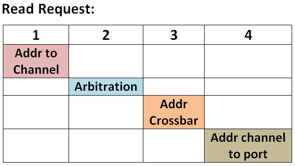
Forward Transfer: (4 cycle)
1. 1 Cycle - Master port to Address Channel
2. 1 Cycle - Arbitration Grant
3. 1 Cycle - Address channel transfer through crossbar
4. 1 Cycle - Address channel to Slave port
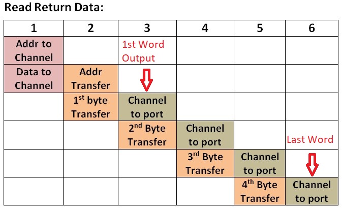
Backward Transfer: (Return Data)
N +2 Cycle - N
data burst (eg: 8 byte Burst and 32 byte request - 4 cycle data
transfer) , 1 Cycle for slave port to channel and 1 Cycle for Channel
to master port
Write
request operation:
1. Master
will request the bus arbiter
2. Arbiter
grant the master based on availability and the Arbitration algorithm.
3. Data
will be transferred from master to slave
4. Slave
will send the first word of the data to slave device.
5. Slave
can handle other transactions during the data is writing to the slave device.
This can be achieved by Read_Threshold and Write_Threshold parameter.
6. Acknowledgment
for the write is completed can be obtained from slave device (based on the
A_Task_Flag field). This response will be forwarded to the master.
7. Master will sends out the ACK immediately.
Standard internal delay - Write
Forward Transfer:
N +3 Cycle - N data
burst (eg: 8 byte Burst and 32 byte request - 4 cycle data transfer) ,
1 Cycle for master port to channel, 1 Cycle for arbitration and 1
Cycle for channel to slave port
1. Output will be issued after 4 cycle as first word out.
2. Last Word will be completed internally after 7 cycle delay
Pipeline Flow:
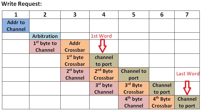
Backward Transfer: (Return response, 3 Cycle)
Pipeline Flow:
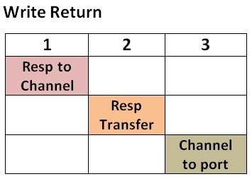
For flows like Sequential Read, Sequential Write, Read followed by Write and Write followed by Read, delaywill be vary
This includes buffering delay due to Slave busy. Arbitration to each request will be based on the availability of the slave and the arbitration algorithm
selected.
If the slave is busy then the packet will be waiting in the master. Once the request is granted, the sequence of delays will be same as the standard delays.
VS_AR/Demo/Bus_Std/AHB_AXI:
1.
AXI_Bus.xml
2.
AXI_Bus123.xml
3.
AHB_AXI_Bus.xml
4.
Multi_AXI_HWDRAM.xml
5.
multi_inp_demo.xml
6.
Simple_AXI_Bus.xml
7.
Simple_AXI_Bus_FixedArbiter_A_Priority_Variable.xml
8.
Simple_AXI_FixedArbiter_Modified_Diff_A_Priority.xml
9.
Simple_AXI_Model_V8.xml
10.
Simple_AXI_RR.xml
11.
Single_AXI.xml
| Parameter |
Explanation | Example | |
| Architecture_Name |
It
refers the Architecture_Setup name. Please keep both the names as same. It can
be linked to top level parameter. |
"Architecture_1" | |
| Bus_Name | Unique name for this Bus. Different from all architecture blocks and global model memories. | "AXI_Top" | |
Key Parameters for Configuration
|
|||
| AXI_Speed_Mhz | Speed of the bus in terms of Megahertz. It can be linked to the top level parameter. | 1000.0 | |
|
Cycle time for all the Master ports are defined using the AXI_Speed_Mhz parameter. | 1.0E-06 / AXI_Speed_Mhz | |
| Bus_Width |
It
defines the maximum bytes that the AXI bus can transfer within a single cycle.
User can define the value based on the requirement. It can be linked to top
level parameter. |
8 | |
| Read_Threshold |
It
defines the Maximum outstanding Read Request that the AXI bus can transfer from
any master to one slave. If the Read request for a particular
slave reached the threshold then the bus cannot send any data to that slave. | 2 | |
| Write_Threshold |
It
defines the Maximum outstanding Write Request that the AXI bus can transfer
from any master to one slave. | 2 | |
| Master_Request_Threshold |
It
defines Threshold value for each master. If the Request (Read/Write) coming to
the specific master has reached the threshold then the AXI will drop the
incoming request. | {2,2,2,2,2,2,2,2,2,2,2,2,2,2,2,2} | |
| Number_Masters | It defines the number of actively configured masters that are connected to the AXI. |
16 | |
| Number_Slaves | It defines the number of actively configured slaves that are connected to the AXI. | 12 | |
| Threshold_Trans_T_Bytes_F |
It
defines the Mode of Transaction in the AXI. If it set to true, then the bus
will perform the transfer in terms of request threshold eg: Threshold values
can be 2,3,4,.etc. If the parameter is set to false,
then the AXI will perform the transfer based on the byte threshold.
Following
are the example for byte based threshold 1. Read_Threashold
= 32 2. Write_Threashold
= 32 3. Master_Request_Threashold
= {32,16,32,32,32,8,64,32,2,2,2,2,2,2,2,2} | true | |
| Arbiter_FIX_1_RR_2_CUSTOM_3 |
It
defines the Scheduling algorithm in the AXI between masters to slaves.. if
value 1 is given then Fixed_Priority algorith will be used. if value 2 is given, then Round
Robin algorithm will be used. if Value 3 is given then users
custom algorithm can be used, which can be implemented by right click on the block -> open block -> right click on the script under "Custom Request Arbiter" ->open block -> (user can impklement thier algorithm here). OR the Custom_File with algorithm can be used. | 1 | |
| Slave_Speeds_Mhz | It defines the speed of the each slave in this AXI bus. This can be used to define the clock cycle and internal timing of each slave. Each index is for the slave ports in order. | {AXI_Speed_Mhz, AXI_Speed_Mhz, AXI_Speed_Mhz, AXI_Speed_Mhz,AXI_Speed_Mhz, AXI_Speed_Mhz, AXI_Speed_Mhz, AXI_Speed_Mhz, AXI_Speed_Mhz, AXI_Speed_Mhz, AXI_Speed_Mhz, AXI_Speed_Mhz, AXI_Speed_Mhz, AXI_Speed_Mhz, AXI_Speed_Mhz, AXI_Speed_Mhz} | |
| Extra_Cycles_for_RdReq_ WrReq_RdData_WrData |
It
defines the overhead delays for each operation in the AXI bus. Each points to
the corresponding operations specified in the parameter. User can put number of delay cycles
based on the requirement. Array with 0 values will not provide any delay to that
operation. | {0, 0, 0, 0} | |
| Devices_Attached_to_Slave_by_Port | This
is a array of arrays. Each array contains the list of devices that are
accessed via a Slave Port. Index 0 of the array is for Slave Port 1,
Index 1 is for Slave Port 2 and so on. There must be one array with one
value for each Slave. The names are strings. AXI
bus uses this information for routing the input request reaching the master. | {{"Cache"}, {"DRAM"}, {"DRAM3"}, {"Device_4"}.......} | |
| Master_Throttle_Enable | It defines the option for choosing flow control
between the AXI master and the master device. If the user set true for specific
master then there will be a flow control maintained. For detail information check the Master throttle enable example | {false, false, false, false, false, false, false, false, false, false, false, false, false, false, false, false} | |
| Slave_Throttle_Enable | It defines the option for choosing flow control between the AXI slave and the slave device. Similar to Master_Throttle_Enable | {false, false, false, false, false, false, false, false, false, false, false, false, false, false, false, false} | |
| DEBUG |
This
will help the user to see how the transaction is happening and the statistics
of the AXI bus. | false | |
| Custom_Arbiter_File | Name of File containing custom arbitration in Virtual Machine script. | "Custom_Script.txt" | |
| Custom_Arbiter_Path | Path to the custom arbitration script file. | "C:/VisualSim/Scripts for Windows /VisualSim/Scripts for UNIX" | |
| Fixed_Priority_Array |
This
is a 2D array. Each index of this Parameter corresponds to each slave.
Since we can have a max of 16 masters on VisualSim AXI Bus Module, each
of the array at slave index will also have a max length of 16. This 16
length array has to be configured in such a way that the max priority
master port number should be at the starting of the array. Example: If one of the array index is defined as {5,7,3,4,1,6,2,8,9,10,11,12,13,14,15,16}, then this means that priority order for masters to send to that slave will be Master 5, then Master 7, then Master 3, then Master 4, then Master 1 etc.....
|
{{1,2,3,4,5,6,7,8,9,10,11,12,13,14,15,16},
{1,2,3,4,5,6,7,8,9,10,11,12,13,14,15,16},.......,
{1,2,3,4,5,6,7,8,9,10,11,12,13,14,15,16}} |
|
| Ports_to_Plot |
This
will enable the AXI to generate ploting information for specific master and
slave. User can observe the Timing diagram for the internal operations. |
{0,0} | |
Only
one outstanding request will reach the master, when the master becomes free
after transferring the data to slave then the next request will reach the master.
To establish the flow control, user
wants to add a field names "Event_Name". The Master device should
send first request and wait for the virtual event from the AXI master.
User can implement throttle control
to specific master or slave and keep the remaining connections as same.
Following are the implementation
example(in script block) for Independent Flow control.
Event
= "Master_Flow_Ctrl"
First_Word
= true
LABEL:BEGIN
-----
-----
port_token.Event_Name
= Event
-----
-----
QUEUE("Flow_Control_Queue",port_token,0,put)
if(!First_Word){
EXIT
}
First_Word = false
LABEL: Loop
Data_ Structure
=QUEUE("Flow_Control_Queue",pop)
SEND(output,Data_Structure)
TIMEQ(Event)
len = QUEUE("Flow_Control_Queue",length)
if(len== 0)
First_word = true
EXIT
}
GTO(Loop)
|
Data Structure Field |
Value (Data Type) |
Explanation |
|
A_Bytes
(necessary) |
100 |
This is the total bytes to be transfered for this transaction. All bursts of this transaction will have this value. |
|
A_Command (necessary) |
"Read" or "Write" |
This determines the operation. |
|
A_Priority (necessary) |
2 |
This is priority of the transaction. The transactions waiting for service are reordered based on this value. |
|
A_Source
(necessary) |
"Processor" |
This is unique name of the Source. When the transaction returns from the Destination, the Source and Destination names are flipped. So, the Source becomes the Destination and Destination becomes Source. |
|
A_Destination (necessary) |
“DRAM” |
Final Destination |
|
Port Name |
Type |
Explanation |
|
input, input2, input3, input4, input5, input6, input7, input8, input9, input10, input11, input12, input13, input14, input15, input16 |
Multiport or input/output. Connection must be made in order- first input to this port and then output away from this port. |
Each port is for a Slave. Transaction Data Structure of type Processor_DS. |
|
output, output2, output3, output4, output5, output6, output7, output8, output9, output10, output11, output12, output13, output14, output15, output16 |
Multiport or input/output. Connection must be made in order- first input to this port and then output away from this port. |
Each port is for a Slave. Transaction Data Structure of type Processor_DS. |
|
Description |
A_Command |
A_Bytes |
A_Bytes_Remaining (optional) |
A_Bytes_Sent (optional) |
|
100 Byte Read at Slave. Bus Width = 4 |
Read |
100 |
96 |
4 |
|
100 Byte Read Return at Master |
Write |
100 |
0 |
100 |
|
100 Byte Write at Slave |
Write |
100 |
0 |
100 |
The following image shows the right way to connect the AXI (16x16) in the Architecture. Source like Processor and DMA can be connected directly to the AXI master port, but if the Master device is designed with simple library block(as logic) then user has to include Device Interface block to provide the interface with master. Similarly for Slave. Slave like RAM, Integrated cache and display can be connected directly to the slave port.
The Bridge block plays important role in connecting the different buses in the architecture. Two buses can not be connected directly, user has to use Bridge block.
Statistics
| DISPLAY AT TIME ------ Part 1 ------ {DS_NAME = "AXI_Level_2_Detected_OverFlows"} DISPLAY AT TIME ------ Part 2 ------ {AXI_Level_2_Master_1_Wr_Data_Bytes = 256, AXI_Level_2_Master_1_Wr_Data_MBps = 51.2, AXI_Level_2_Master_2_Rd_Data_Bytes = 64, AXI_Level_2_Master_2_Rd_Data_MBps = 12.8, AXI_Level_2_Slave_2_Wr_Data_Bytes = 256, AXI_Level_2_Slave_2_Wr_Data_MBps = 51.2, AXI_Level_2_Slave_3_Rd_Data_Bytes = 64, AXI_Level_2_Slave_3_Rd_Data_MBps = 12.8, DS_NAME = "AXI_Level_2_Rd_Wr_MBps"} DISPLAY AT TIME ------ Part 3 ------ {AXI_Level_2_Slave_3_Rd_Threshold_Usage = 1.0, AXI_Level_2_Slave_Transactions = 2, DS_NAME = "AXI_Level_2_Slave_3_Rd_Threshold"} DISPLAY AT TIME ------ Part 4 ------ {AXI_Level_2_Slave_2_Wr_Threshold_Usage = 1.0, AXI_Level_2_Slave_Transactions = 8, DS_NAME = "AXI_Level_2_Slave_2_Wr_Threshold"} DISPLAY AT TIME ------ Part 5 ------ {BLOCK = "AHB_AXI_Bus.AMBA_AXI4.Master_1.Master", DS_NAME = "Master_Transactions_1", Number_Entered = 8, Number_Exited = 8, Occupancy_Max = 1.0, Occupancy_Mean = 0.5, Occupancy_Min = 0.0, Occupancy_StDev = 0.5} DISPLAY AT TIME ------ Part 6 ------ {BLOCK = "AHB_AXI_Bus.AMBA_AXI4.Slave_2.AXI_Level_2_Slave_Out_Queue", DS_NAME = "Slave_Transactions_2", Number_Entered = 8, Number_Exited = 8, Occupancy_Max = 1.0, Occupancy_Mean = 0.5, Occupancy_Min = 0.0, Occupancy_StDev = 0.5, Total_Delay_Max = 3.01E-8, Total_Delay_Mean = 2.6755555555556E-8, Total_Delay_Min = 0.0, Total_Delay_StDev = 9.4595173838734E-9} |
Part 1 Shows the number of transactions that were dropped for each Master. Part 2 First section shows the number of read/write data in bytes for each Master. Second shows the MBps for read/write for each Master. Last section shows the number of read/write data in bytes for each Slave. Last shows the MBps for read/write for each Slave. Part 3 Shows the read threshold usage and the Threshold value set in the parameters of the block. This is shown separately for each Slave. Part 4 Shows the write threshold usage and the Threshold value set in the parameters of the block. This is shown separately for each Slave. Part 5- One for each master Shows the statistics for each Master Part 6- One for each Slave Shows the statistics for each Slave |
Debug
| DISPLAY AT TIME ------ 19.00 ns ------ AXI_Level_2 Master_2 Rd_Request Src: uProcessor Des: DDRDRAM3 Size: 32 Master_2 Increment Rd_Requests: 1 Wr_Requests: 0 Master_Req_Threshold: 2 DISPLAY AT TIME ------ 30.00 ns ------ AXI_Level_2 Arbiter Slave_3 Increment Rd_Requests: 1 Rd_Threshold: 8 Arbiter Master_2 Decrement Rd_Requests: 0 DISPLAY AT TIME ------ 30.00 ns ------ AXI_Level_2 Slave_3 Rd_Transaction Src: uProcessor Des: DDRDRAM3 Size: 32 DISPLAY AT TIME ------ 60.00 ns ------ AXI_Level_2 Master_2 Rd_Transaction Src: DDRDRAM3 Des: uProcessor Size: 32 DISPLAY AT TIME ------ 78.10 ns ------ AXI_Level_2 Master_2 Slave_3 Decrement Rd_Requests: 0 Rd_Threshold: 8 DISPLAY AT TIME ------ 2.91100 us ------ AXI_Level_2 Master_1 Wr_Request Src: DMA Des: DDRDRAM2 Size: 32 Master_1 Increment Wr_Requests: 1 Rd_Requests: 0 Master_Req_Threshold: 4 DISPLAY AT TIME ------ 2.92800 us ------ AXI_Level_2 Slave_2 Wr_Transaction Src: DMA Des: DDRDRAM2 Size: 32 DISPLAY AT TIME ------ 2.94600 us ------ AXI_Level_2 Master_1 Wr_Transaction Src: DDRDRAM2 Des: DMA Size: 32 DISPLAY AT TIME ------ 2.94610 us ------ AXI_Level_2 Arbiter Slave_2 Increment Wr_Requests: 1 Wr_Threshold: 8 Arbiter Master_1 Decrement Wr_Requests: 0 DISPLAY AT TIME ------ 2.94610 us ------ AXI_Level_2 Slave_2 Decrement Wr_Requests: 0 Wr_Threshold: 8 |
19;00ns Displays the current time Diaplays the name of the AXI Bus Master Port Number- Master_2 Request Type- Rd and Wr Source- Src: uProcessor Destination- Des: DDRDRAM3 Request Size- 32 Increment states whether it is incrementing the Threshold counting or Decrement which is decreasing the count. Provides the number of outstanding Requests for this Master and the Destination Slave. 30.00 ns Increment the counter for the Read/Write request and the read threshold. Decrement the counter for the Request |
1. VisualSim.kernel.util.InternalErrorException:
Cannot create receivers
in .<Unnamed Object>.AMBA_AXI
Because:
Cannot
create a receiver without an executive director.
2. Error : Issue with RegEx execution
Exception :
VisualSim.kernel.util.IllegalActionException: Error invoking function
public static java.lang.String
VisualSim.data.expr.UtilityFunctions.throwMyException(java.lang.String) throws VisualSim.kernel.util.IllegalActionException
Because:
User
RegEx Exception:
AXI_Top_Master_2
did not find Slave named DRAM
on
port number: 2 from Source: Processor2
Check
Device_Attached_to_Slave_N parmeters
Make sure the "Device_Attached_to_Slave_by_Port" parameter contains the connected slave names.
Make sure the destination name is correct.