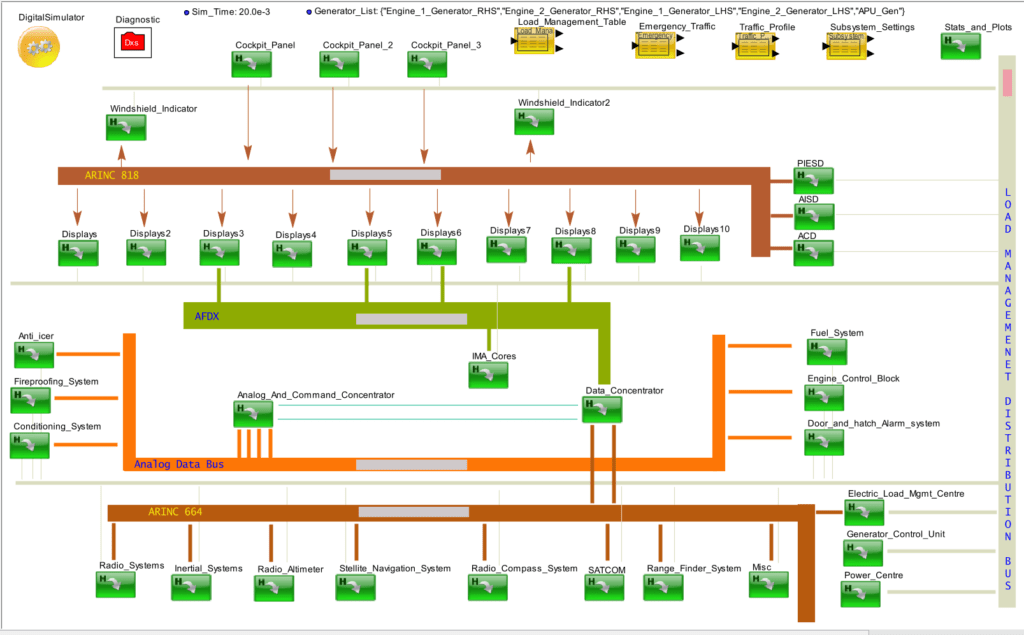
Prior generation of avionics were built with a specific use-case in mind. The resources were sized efficiently to match the avionics application requirements for performance, functionality, and failure. These designs were tested using reference boards provided by the vendor. The new generation of avionics have dynamic requirements with multiple use-cases, more instruments, and faster interfaces. Rather than building a new semiconductor device or an avionics system for each use-case, we needed to build one architecture that encompasses all the use-cases while maintaining diametrically opposing needs. For example, if we change the number of IMA cores, the performance of other subsystems should not degrade, even though they share resources. We used a system modelling and simulation platform to create a base template of the avionics system. We created a stereotype for each sub-system and multiple profiles for each. We simulated these different profiles across all the use-cases and selected the system specification that handled most of the use cases. The traditional requirements were to meet throughput and latency. We added failure analysis to determine the single and multiple points of failure. The profiles, use-cases and the test cases were provided to the integration company for a closed loop communication.
VisualSim Architect Model:
 Architecture Exploration of Avionics Systems to optimize the specification, validate requirements and test for failures
Description:
The model above represents the system level schematics of a next gen aircraft communication and electrical system. It covers all the relevant subsystems ranging from Fuel system, Generators, Displays and all the way till SATCOM (Satellite communication systems) and IMA (Integrated Modular Avionics) Cores. Using this system model, the architect can evaluate the performance and power consumed per each subsystem for different test scenarios which are not easily replicated in a test lab environment. That is because, in a lab environment, scaling up the subsystems or evaluating faulty scenarios are a tedious task. But with system model, any such requirements can be achieved by simply updating the parameter configurations. Redundancy (Dual and Triple), Load management, load shedding, Emergency traffic patterns are included and can be configured as required to match the test scenarios. The system model also includes a requirement tracker which can be used by the architect to define a set of requirements that must be achieved while running different test scenarios.
This demo model also includes a fault injection mechanism which lets the architect evaluate the performance of the full system as well as the subsystem in the presence of various faults. For example – what happens if the voter in the triple redundancy is unable to cast a clear vote? Can the high priority subsystems function properly in the presence of multiple generator failure? How does the emergency traffic such as the Anti-icer or hatch alarm affect the performance of other subsystems, as many resources such has buses and IMA cores are shared?
Unlike the text based models that an architect is usually familiar with, this model is built on a graphical platform where the subsystems are assembled without the use of complex programming languages. This makes it easy for an architect to interpret and use the system model. Since the system model can be made available much early in the design process, this allows the architect and the entire team involved in the design and testing process to gain insight on possible challenges that would arise in different test scenarios and prepare the solutions accordingly.
In a big system such as the avionics system, a number of different teams will be working in parallel to determine the best configurations for each subsystem they are responsible for – Systems Team for Flight control, Radar systems, Satellite communication, Load management system, Displays, Cockpit panels, Anti-icer, conditioning systems etc. Each team focuses on a particular part of the system they are assigned with. But at the time of assembling the systems together and perform tests, they find a lot of issues which were not known before. This pushes the schedule back as well as additional resources and cost needs to be spent to resolve them. So for engineers working on a big system such as the avionics, having a single system model of the complete avionics system is hugely helpful and very much valuable. Each engineering team could focus on building their subsystem and run different test cases. Now that all teams are sharing a single model, the architects can observe whether the traffic or resource usage from other subsystems affect the performance/power of the module they are responsible for.
Once the base model and common traffic patterns and scenarios were verified, the architects can inject various faults into the system model and evaluate whether the requirements are being met in the presence of various faults. This can help identify faults and bugs which could prevent the sanction of safety and security certifications.
Conclusion
As each team builds up/assembles their subsystem, the traces from those subsystems can be used to replace the system model version of the corresponding subsystems. Faults can again be injected and the impact on other subsystems are observed. Even after the project gets completed, the system model of the assembled avionics system provides a huge value for the engineers working on next gen versions of the same system in the future years as the new team can then start work using the same system model as template and add improvements to the subsystems of choice.