Power Modeling and Analysis using VisualSim Architect

Example

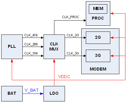
This is an example of the power modeling using a set of standard VisualSim library blocks and a custom behavior flow diagram. The following base system has been selected for the demo.
Demo Details

The following has been considered while modeling :-

State Table:

STATE

OFF

SLEEP

2G

3G

PLL

OFF

ON

ON

ON

CLKMUX

OFF

SLEEP

2G

3G

2G

OFF

OFF

ACTIVE

SLEEP

3G

OFF

OFF

SLEEP

ACTIVE

PROC

OFF

IDLE

2G

3G

BAT

1,0

1,0

1,1

1,2

LDO

ON

ON

ON

ON

 Computation of Current for each device in each state:

2G Block:

states: ACTIVE,SLEEP,OFF
active current:    clk_i*VDDC*NDP(2G,SLEEP)
static current: area*LBV(VDDC)+I_leak_switch(VDDC)  (for off mode only I_leak_switch)
Area:0,3mm² and 400 swicthes

3G Block:

states: ACTIVE,SLEEP,OFF
active current:    clk_i*VDDC*NDP(3G,SLEEP)
static current: area*LBV(VDDC)+I_leak_switch(VDDC)  (for off mode only I_leak_switch)
Area:0,8mm² and 1000 switches

PROC:
states: 3G,2G,IDLE,OFF
active current:    clk_i*VDDC*NDP(3G,SLEEP)+I_access_mem
static current: area*LBV(VDDC)+I_leak_mem+I_leak_switch(VDDC) (for off mode only I_leak_switch)
Area:3,2mm² and 2000 switches
PLL:
states: ON,OFF
active current:    I_act(ON)  ; (fixed val per state)
static current:     fix val(VDDC)
LDO:
states: ON,OFF
I_housekeeping  = no_load_current + eff_factor*Iload
I_drawn = Iload + I_housekeeping
CLKMUX:
States: 
3G(clk_2G=104, clk_3G=208, clk_PROC=416Mhz)
2G(clk_2G=208, clk_3G=104, clk_PROC=208Mhz)
SLEEP(clk_2G=0, clk_3G=0, clk_PROC=104Mhz)
OFF (all clks=0)
active current:   I_act(3G,2G,SLEEP,OFF)  ; (fixed value per state)
static current:    fix value(VDDC)

Technology/design  data 

NDP: Normalized Dynamic Power (µA/Mhz/V) Variable

 LBV: Leakage Base Value (µA/mm²)

1,0V    3,0E-11
1,1V    4,5E-11
1,2V    7,0E-11

Switch leakage (per switch)1,0V    1,9E-10
1,1V    3,5E-10
1,2V    6,0E-10

Simulation

A number of simulation variations have been constructed to demonstrate the usage.  The first is the one below.  The others are on separate pages.
Hierarchical View of 2G, 3G, Processor and Battery. No simulation run possible
Parameters + Reports only. To run the simulation, click Go in the below applet.

Top-level Model and the Simulation Plots

The model of example system is embedded below.  To run the simulation, click Go in the below applet.

References

[1] VisualSim documentation, Mirabilis Design
Copyright 2011 © Mirabilis Design Inc. All Rights Reserved.