Configuring the STK_Port block
To configure the STK_Port block, right click the block and select Configure. The following window is displayed to configure the parameters.

Figure 1. Sending individual command to STK
Single file can be used to send the group of commands. The commands to be sent to the STK can also be stored in a text file. The path should be specified. For If VisualSim has been installed on Drive C, then your STK_Command_Data parameter may be like:
"ConFile /E:/VisualSim/VS/VisualSim/interfaces/stk/connect_demo_begin.txt"
Click View in the menu bar and select Simulation Cockpit (Refer Figure 2). This is an optional process to run the model. You can also run the model by clicking Run Icon or Ctrl+R.
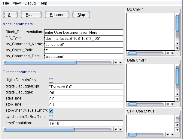
Figure 2. Simulation Cockpit
Note: Start STK manually and create a scenario before running the command. Otherwise, an error message is displayed.
This creates a new satellite in the STK tool.
Now right click the block, then click Configure, and give following values for the fields.
Note: If you receive an error message after entering the STK_Command_Path_Data, then check for the parameters related to this field. For example: My_Command_Name: "concontrol", My_Object_Path: "/" and My_Command_Data: "verboseon". Delete the parameter value and then enter "New / */Satellite Sat1".
To monitor the values when the command is run, click View in the menu, and select Simulation cockpit. The model can also run by clicking Play on the tool bar. After this command is passed, a new satellite is created. The following screenshot is from the STK tool.
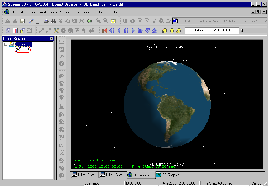
Figure 3. Screenshot from STK tool
This is the third command to be entered. The Set Classical command with the following parameters is used to define the satellite's orbit using Classical (Keplerian) elements: Now right click the block, then click Configure, and give the following values for the fields. Refer figure 4.
Note: If quotes occur within in a command then it should be preceded by a \ (backslash).
Figure 4. Edit Parameters for STK_Port
Run the command from the Simulation Cockpit, and monitor the values form there (Refer Figure 2). Click Play in the tool bar. Now properties for the satellite are created.
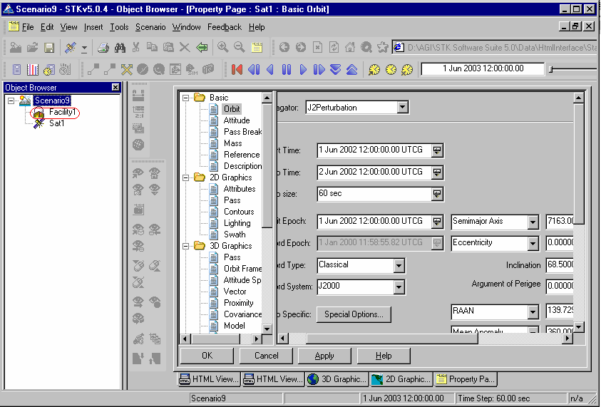
Figure 5. STK tool
Use the New command again to create a new facility. Right click the block and enter the following values for the fields:
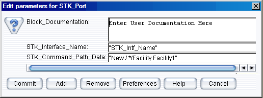
Figure 6. Creating new facility object
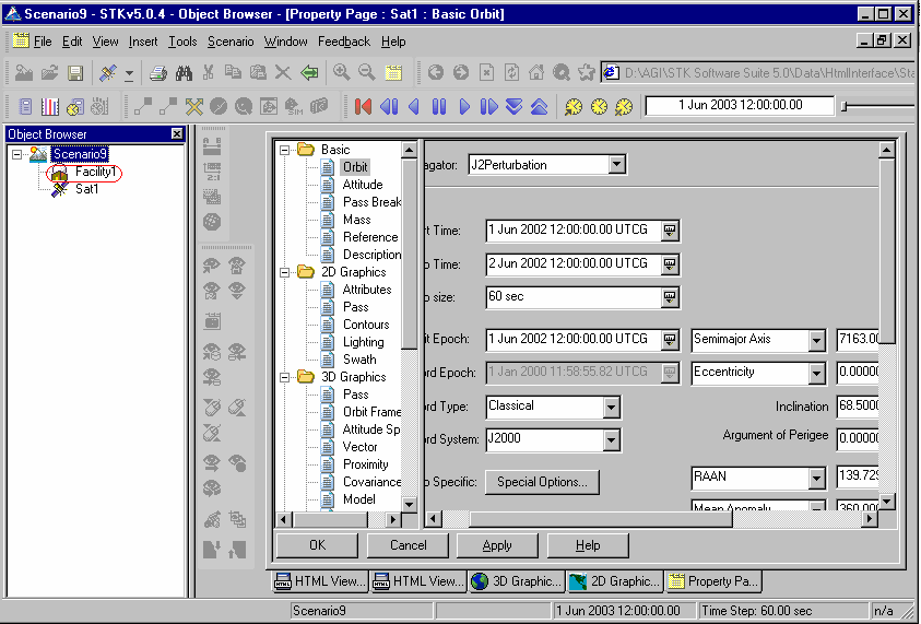
Figure 7. STK Tool
Then define its position using the SetPostion command:
SetPosition */Facility/Facility1 Geodetic 37.9 -75.5 0.
Now right click the block, then click configure, and give following values for the fields.
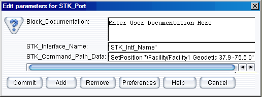
Figure 8. Set the position of the facility object
Click Commit to save the changes.
Run the command from the Simulation cockpit, and monitor the values or click Play in the tool bar.
The Access command with the following parameters is used to calculate access from the facility to the satellite:
Right click the block, select Configure, and give the following values for the fields.
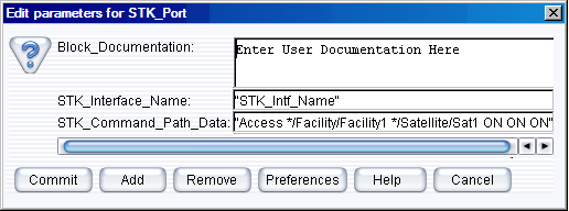
Figure 9. Set the STK_Command_Path_Data
Click Commit to save the changes.
Run the command from the simulation cockpit, and monitor the values from there, else click Play in the tool bar. The following screenshot is from the STK tool.
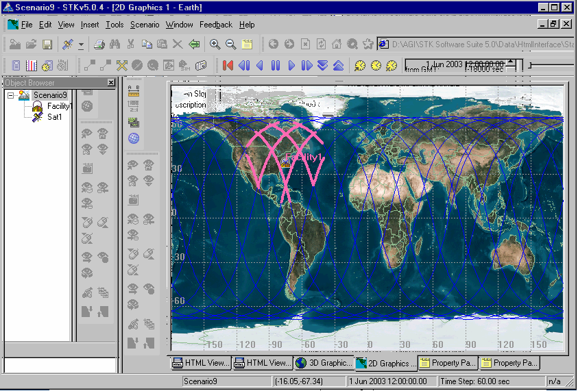
Figure 10. Screenshot from the STK tool
This command starts the animation in the STK. Now right click the block, then click configure, and give the following parameters.
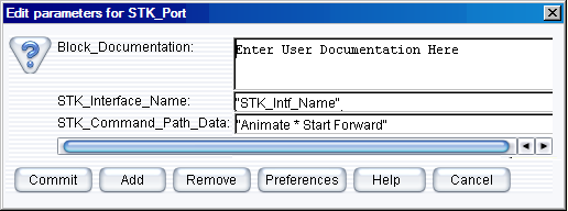
Figure 11. Set the parameter STK_Command_Path_Data
Click Commit to save the changes.
Run the command from the simulation cockpit and monitor the values. Else, click Play in the tool bar. After this is done, the animation is started in the STK tool.
The Animate command is used again to stop the animation and reset the Map window graphics:
Right click the block and select Configure. Enter the following parameters:
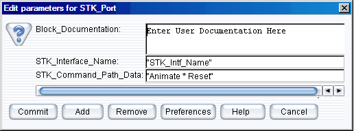
Figure 12. Animate the current STK Scenario
Click Commit to save the changes.
Run the command from the Simulation cockpit and monitor the value. Else, click Play in the tool bar. This resets the animation in the STK tool.
This creates reports and graphs from the block. Now right click the block, click Configure, and give the following parameters.
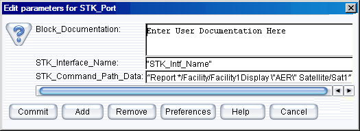
Figure 13. Generate report for the scenario
Click Commit to save the changes.
Run the command from the Simulation cockpit and monitor the value. Else, click Play in the tool bar. After this is done, the animation is started in the STK tool. Report is generated after execution of this command.

Figure 14. STK Tool
Instead of entering the commands individually, multiple statements can be entered. Save this in VisualSim directory. For example, C:/VisualSim/VS/VisualSim/interfaces/stk. Specify the file name as connect_demo_begin.txt.
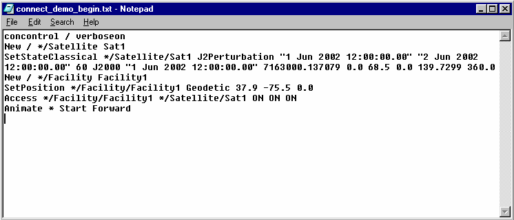
Figure 15. Commands in a text file
Now, the STK_port block has to be configured. Right click on the block, click Configure, and enter the following parameters.
Note: If the Install Folder is different, then save it in the respective path.

Figure 16. Sending sequence of commands in a file
Click Commit and run the command from the simulation cockpit to monitor the values. Else, click Play in the tool bar. After this is done, the animation is started.
Now to reset the animation, enter the following commands in a text editor and save it as connect_demo_end.txt in E:/VisualSim/VS/VisualSim/interfaces/stk (Change the path for your machine).
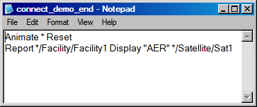
Figure 17. connect_demo_end.txt file
Now, the STK_port block has to be configured again, before selecting Play. Right click on the block and click on configure and enter the following parameters.
Click Commit. Run the command from Simulation cockpit to monitor the values, click Play in the tool bar. After this is done, the animation is reset and a report is generated in the STK tool.