Embedded system designers have a choice of using a shared or point-to-point bus in their designs. Typically, an embedded design will have a general-purpose processor (ARM or PowerPC), GPU, Accelerator, cache, SDRAM, DMA, and Bridge to a slower I/O bus, such as the Advanced Microcontroller Bus Architecture (AMBA) Advanced Peripheral Bus (APB). In addition, there might be a port to a separate DSP processor, or hardware accelerator, to convert formats and generating drawing commands. As chip-level device geometries become smaller and smaller, more and more functionality can be added without the concomitant increase in power and cost per die as seen in prior generations.
System Modeling enables product teams to explore and trade-off different architectures to meet timing, throughput and power consumption. System modeling can be used prior to software or hardware code development, thus ensuring that all bottlenecks and bugs have been identified before development. A thorough validation of the system specification saves considerable development time and allows for more design exploration prior to selecting a topology to begin implementation.
This paper compares the use of AMBA Advanced High-performance Bus (AHB) Shared Bus and AMBA Advanced eXtensible Interface (AXI) by modeling the entire system using VisualSim. The graphical model and simulation analysis was completed in approximately one week.
To make the evaluation of the two buses comparable in terms of flow, throughput, and latency, the following considerations were adopted:
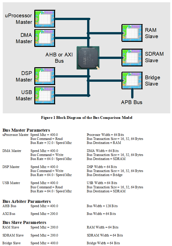
- The AHB is a single-channel, shared bus. The AXI is a multi-channel, read/write optimized bus. Each bus master, or requesting bus port, connects to the single-channel shared bus in the AHB, while each AXI bus master connects to a Read address channel, Read data channel, Write address channel, Write data channel, and Write response channel. The primary throughput channels for the AXI are the Read/Write data channels, while the address and response channels are to improve pipelining of multiple requests. Assume there are four masters on each bus going to three slaves. The four master ports are uProcessor, Direct Memory Access (DMA), DSP, and USB. The three slaves are on-chip RAM, off-chip SDRAM DDR3, and an APB bus bridge.
- To compute the bandwidth of the two buses, one must count the number of read/write channels of the AXI Bus – six for three bus slaves. This suggests that the AHB Bus should support some multiples of bus width and/or speed to match the data throughput. The System Model can vary these combinations with simple parameter changes. However, AHB bus speed was assumed to be double that of the AXI Bus, and two times its width. This will make the comparison of the two buses more realistic.
- To evaluate the efficiency of the buses, different burst sizes were selected; small, medium, and large. Small equates to the width of the AHB Bus, medium equates to two AHB Bus transfers, and large equates to four AHB Bus transfers.
- The AXI is a 64-bit bus running at 200 MHz, and the AHB is 128-bit bus running at 400 MHz. The burst sizes are small (16 Bytes), medium (32 Bytes), and large (64 Bytes).
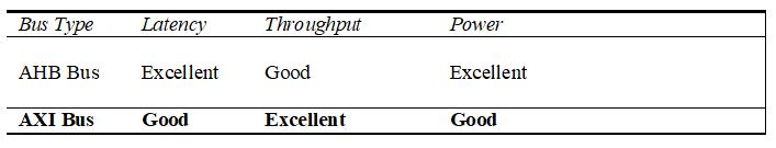
The focus of this paper is on the requirements for quick model construction, attributes to be monitored and workloads to be generated. The design goal is to select the bus that performs best in terms of throughput, latency, and utilization for single or multiple channels. The analysis compares the two bus technologies side by side for 16, 32, and 64 Byte transfers. The average per channel utilization is used to measure power consumption.
While the AXI Bus has multiple read/write channels to improve performance, and should perform better on average and peak latency measurements; the concurrent internal bus transfers will impact the performance. The shared AHB Bus efficiency is impacted by the arbitration algorithm. The System Level Model will provide insights into both the buses, such that a designer could select the right bus for the application.
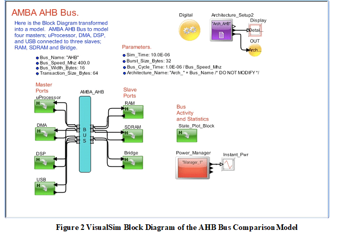
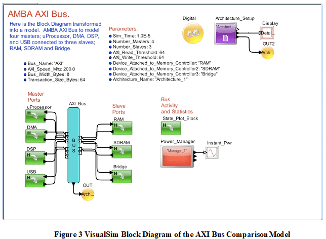
For this modeling exercise, we used a standard software application called VisualSim from Mirabilis Design Inc. This is a concept engineering software application that enables rapid prototyping of embedded systems for performance and power trade-off. We could create models in the VisualSim using the configurable, parameterized library blocks, application-specific functions, and standard component generators (processors, memory, caches, bus and switches). The VisualSim optimizes the initial concept through a series of modeling refinements and abstractions to allow the best architecture to become an executable specification.
System Model Overview
The AHB Bus Comparison Model is shown in Figure 2 and the AXI Bus Comparison Model is shown in Figure 3. The system model consists of the following:
- uProcessor, DMA, DSP, and USB Master bus ports.
- AHB, or AXI Bus Arbiter.
- RAM, SDRAM, and Bridge Slave bus ports.
- Result plots and window displays for statistics.
Modeling Results
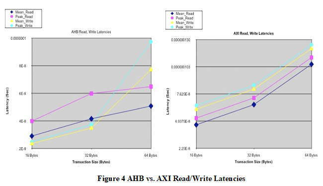
The AHB Bus latencies start out lower than the AXI Bus at 16 Byte transaction size and the AHB Bus does not exceed the AXI Bus at 64 Byte transaction size. Based on the plot trends, the AXI Bus will have lower latencies above 128 Byte transaction sizes. Note: the y-axis scale is different in Figures 5 and 6.
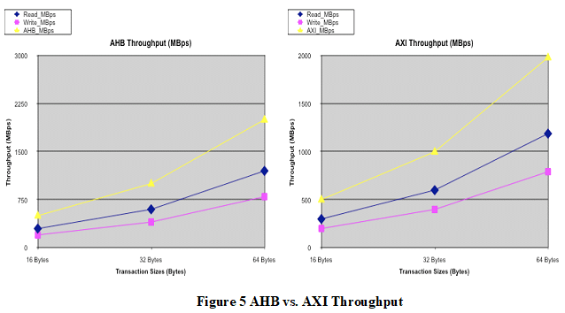
The throughput plots are identical, which is expected if both have the same source traffic rates and sizes.
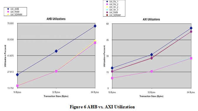
The AHB Bus utilization is higher than that of the AXI Bus channels for all transaction sizes, which is expected since the AXI Bus has six channels. The percentage values for the AXI Bus do not track the AHB Bus since it is running at one-half the speed and width of the AHB Bus.
Analysis
VisualSim was able to provide the necessary plots to compare the two buses. The latency plots show that the AHB Bus can provide comparable, or lower latencies up to 64 Byte transaction sizes. The AHB Bus is running at twice the speed and double the width. The throughputs are similar for the same traffic sources. The utilizations are higher for the AHB Bus, as the AXI Bus has six read/write channels. In terms of power, the single AHB should be approximately 4X a single AXI Bus channel, given the speed and width. Since there are six AXI Bus channels, plus some additional channels, the AXI Bus should consume approximately 1.5X the power of the AHB Bus.
Design Impacts
As a result of this bus model comparison, some bus design considerations emerge:
- Consider the peak utilization of a bus channel. If the model shows the peak loading is in the 70% to 80% range, then the bus will sustain additional traffic without redesign.
- Consider the peak latency for a critical path, such as uProcessor to RAM. Will the peak latency allow the design to meet its overall timing objectives, such as a video frame rate?
- Consider the power consumption of the bus topology. Can a shared bus reduce power consumption?
Results
The AHB Bus performed best for the given traffic rates and sizes. The AXI Bus was rated higher for throughput, even though the comparison was the same for both models since it has additional capacity. The AXI Bus would use approximately 50% more power, assuming similar process technology, again giving the edge to the AHB Bus.